Difference between revisions of "Projects/Diffusion/Contrasting Tractography Measures/Slicer Tractography"
| (33 intermediate revisions by the same user not shown) | |||
| Line 1: | Line 1: | ||
| − | + | ====Whole Brain Seeding==== | |
Whole brain seeding followed by selection between two ROIs. Using eddy-corrected data set, without downsampling. | Whole brain seeding followed by selection between two ROIs. Using eddy-corrected data set, without downsampling. | ||
Tensor estimation in DTMRI module in Slicer 2.8. | Tensor estimation in DTMRI module in Slicer 2.8. | ||
| − | + | The automatic brain mask generated in conversion step is used to prevent tracking in ventricles and outside the brain. | |
| − | Tracts are seeded at a resolution of 2mm at points where cL > 0.3; tracking stops when cL drops below 0.15. | + | Tracts are seeded at a resolution of 2mm at points where cL > 0.3; tracking stops when cL drops below 0.15. Tracts shorter than 20mm are discarded. Remaining tracts are saved to disk as separate .vtk files. |
| + | |||
| + | ====Tract selection==== | ||
| + | Using LaurenThesis module in Slicer 2.8, tracts are selected that pass through 2 specified ROIs. | ||
| + | |||
| + | For all cases of the arcuate fasciculus, none of the tracts generated were found to connect the two ROIs along the arcuate pathway. | ||
| + | |||
| + | ====Measurement==== | ||
| + | For all cases, mean scalar measures (FA, mode, trace, linear, planar, spherical) were computed along each individual tract, then combined into a single average measure for each group of tracts. Measurements were done using a Matlab script. | ||
| + | |||
| + | For the cingulum, the three different groups of tracts for each side (L,R) were combined for a single mean measure (note that not all 3 groups were found for every case). | ||
| + | |||
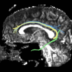
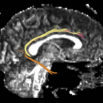
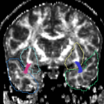
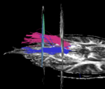
| + | For the uncinate, internal capsule, and fornix, another matlab script was used to cut the tracts where they passed through the ROIs, so that the final measures included only the region of the tracts between the two ROIs. (The pictures below are positioned to show the regions measured; e.g., in the IC pictures, the tracts were measured between the two coronal slices which held the ROIs). | ||
{| | {| | ||
| − | ! Case !! Uncinate Fasciculus !! Internal Capsule !! Fornix !! Cingulum (Left) !! Cingulum (Right) | + | ! Case !! Uncinate Fasciculus !! Internal Capsule !! Fornix !! Cingulum (Left) !! Cingulum (Right) |
|- | |- | ||
| caseD00917 || [[Image:CaseD00917_tracts_cut.png|thumb|150px]] || [[Image:917.png|thumb|150px]] || [[Image:917_fx.png|thumb|150px]] || [[Image:917_cing_L.png|thumb|150px]] || [[Image:917_cing_R.png|thumb|150px]] | | caseD00917 || [[Image:CaseD00917_tracts_cut.png|thumb|150px]] || [[Image:917.png|thumb|150px]] || [[Image:917_fx.png|thumb|150px]] || [[Image:917_cing_L.png|thumb|150px]] || [[Image:917_cing_R.png|thumb|150px]] | ||
| Line 25: | Line 37: | ||
| caseD00935 || [[Image:CaseD00935_tracts_cut.png|thumb|150px]] || [[Image:935.png|thumb|150px]] || [[Image:935_fx.png|thumb|150px]] || [[Image:935_cing_L.png|thumb|150px]] || [[Image:935_cing_R.png|thumb|150px]] | | caseD00935 || [[Image:CaseD00935_tracts_cut.png|thumb|150px]] || [[Image:935.png|thumb|150px]] || [[Image:935_fx.png|thumb|150px]] || [[Image:935_cing_L.png|thumb|150px]] || [[Image:935_cing_R.png|thumb|150px]] | ||
|- | |- | ||
| − | | caseD00936 || [[Image:CaseD00936_tracts_cut.png|thumb|150px]] || [[Image:936.png|thumb|150px]] || [[Image: | + | | caseD00936 || [[Image:CaseD00936_tracts_cut.png|thumb|150px]] || [[Image:936.png|thumb|150px]] || <center>No tracts selected</center> || [[Image:936_cing_L.png|thumb|150px]] || [[Image:936_cing_R.png|thumb|150px]] |
|- | |- | ||
| caseD00938 || [[Image:CaseD00938_tracts_cut.png|thumb|150px]] || [[Image:938.png|thumb|150px]] || [[Image:938_fx.png|thumb|150px]] || [[Image:938_cing_L.png|thumb|150px]] || [[Image:938_cing_R.png|thumb|150px]] | | caseD00938 || [[Image:CaseD00938_tracts_cut.png|thumb|150px]] || [[Image:938.png|thumb|150px]] || [[Image:938_fx.png|thumb|150px]] || [[Image:938_cing_L.png|thumb|150px]] || [[Image:938_cing_R.png|thumb|150px]] | ||
| Line 33: | Line 45: | ||
| caseD00940 || [[Image:CaseD00940_tracts_cut.png|thumb|150px]] || [[Image:940.png|thumb|150px]] || [[Image:940_fx.png|thumb|150px]] || [[Image:940_cing_L.png|thumb|150px]] || [[Image:940_cing_R.png|thumb|150px]] | | caseD00940 || [[Image:CaseD00940_tracts_cut.png|thumb|150px]] || [[Image:940.png|thumb|150px]] || [[Image:940_fx.png|thumb|150px]] || [[Image:940_cing_L.png|thumb|150px]] || [[Image:940_cing_R.png|thumb|150px]] | ||
|} | |} | ||
| + | |||
| + | |||
| + | ====Results==== | ||
Latest revision as of 18:43, 26 September 2007
Home < Projects < Diffusion < Contrasting Tractography Measures < Slicer TractographyWhole Brain Seeding
Whole brain seeding followed by selection between two ROIs. Using eddy-corrected data set, without downsampling.
Tensor estimation in DTMRI module in Slicer 2.8.
The automatic brain mask generated in conversion step is used to prevent tracking in ventricles and outside the brain.
Tracts are seeded at a resolution of 2mm at points where cL > 0.3; tracking stops when cL drops below 0.15. Tracts shorter than 20mm are discarded. Remaining tracts are saved to disk as separate .vtk files.
Tract selection
Using LaurenThesis module in Slicer 2.8, tracts are selected that pass through 2 specified ROIs.
For all cases of the arcuate fasciculus, none of the tracts generated were found to connect the two ROIs along the arcuate pathway.
Measurement
For all cases, mean scalar measures (FA, mode, trace, linear, planar, spherical) were computed along each individual tract, then combined into a single average measure for each group of tracts. Measurements were done using a Matlab script.
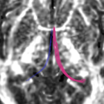
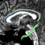
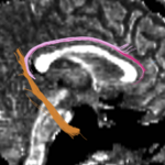
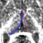
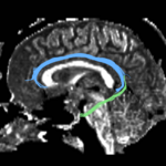
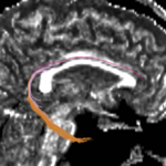
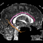
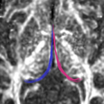
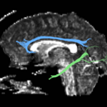
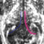
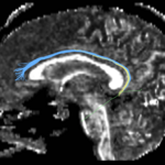
For the cingulum, the three different groups of tracts for each side (L,R) were combined for a single mean measure (note that not all 3 groups were found for every case).
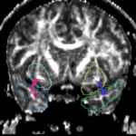
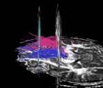
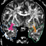
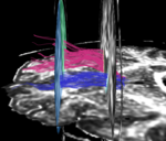
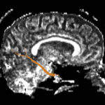
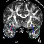
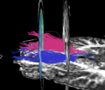
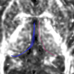
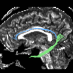
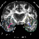
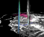
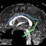
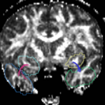
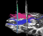
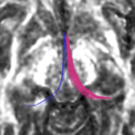
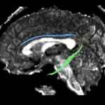
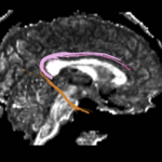
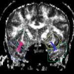
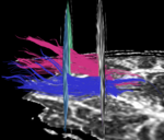
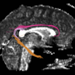
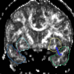
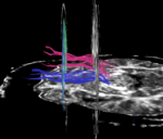
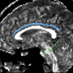
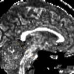
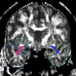
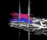
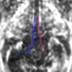
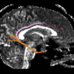
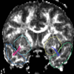
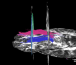
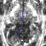
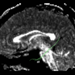
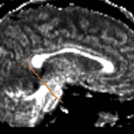
For the uncinate, internal capsule, and fornix, another matlab script was used to cut the tracts where they passed through the ROIs, so that the final measures included only the region of the tracts between the two ROIs. (The pictures below are positioned to show the regions measured; e.g., in the IC pictures, the tracts were measured between the two coronal slices which held the ROIs).
| Case | Uncinate Fasciculus | Internal Capsule | Fornix | Cingulum (Left) | Cingulum (Right) |
|---|---|---|---|---|---|
| caseD00917 | |||||
| caseD00920 | |||||
| caseD00924 | |||||
| caseD00925 | |||||
| caseD00928 | |||||
| caseD00935 | |||||
| caseD00936 | |||||
| caseD00938 | |||||
| caseD00939 | |||||
| caseD00940 |
