Difference between revisions of "Novel Hexahedral Meshing Algorithms"
From NAMIC Wiki
| Line 38: | Line 38: | ||
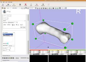
[[Image:Slicer3MeshExample1.png|left|thumb|300px|Bounding Box Mesh Workflow shown in Slicer3 ]] | [[Image:Slicer3MeshExample1.png|left|thumb|300px|Bounding Box Mesh Workflow shown in Slicer3 ]] | ||
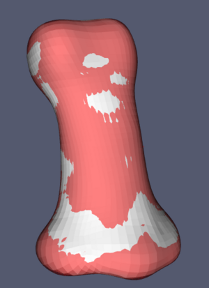
| − | [[Image: | + | [[Image:MappedMeshMiddleIndex.png|left|thumb|300px|FE Mapped Meshing Module showing the subject surface in red and the resulting mesh in white.]] |
Revision as of 21:47, 29 October 2007
Home < Novel Hexahedral Meshing AlgorithmsObjective:
- Develop and integrate novel hexahedral meshing algorithms into the NA-MIC kit
Progress:
- Base projection algorithms have been developed and will be integrated into the toolkit. The algorithms have been implemented in KWWidgets in IaFeMesh to simplify integration into Slicer3.
- The base code and algorithms have been brought into Slicer3 for integration within the GUI and MRML. Curt Lisle has been working on a this integration.
- The sort term goal is to get a single editable bounding box working within Slicer3 for the next release.
- Projection based morphing and mesh interpolation will be required.
- Include export to Abaqus format
- Develop mapped meshing techniques that include an FE based solution using ITK that registers a template mesh with a subject specific surface.
To Do:
- Fully support all bounding box editing options
- Add
- Delete
- Split
- Merge
- Extrude
- Face manipulation
- Extract mesh material properties from the images
- Further evaluate and integrate the mapped mesh algorithms into Slicer3.
Key Investigators:
- Iowa: Nicole Grosland, Vincent Magnotta, Kiran Shivanna, Curt Lisle, and Steve Pieper
Links:


