Difference between revisions of "Projects:DicomToNrrdForDTI"
| (4 intermediate revisions by the same user not shown) | |||
| Line 1: | Line 1: | ||
| − | Dicom conversion for DTI data | + | = Dicom conversion for DTI data = |
| Line 10: | Line 10: | ||
The DTI sequence is a 25 directions with variable b-values plus one B0 image. | The DTI sequence is a 25 directions with variable b-values plus one B0 image. | ||
| − | [[Image:OrigDataBVal.png|400px|right]] | + | [[Image:OrigDataBVal.png|thumb|400px|right]] |
| + | [[Image:OrigGradDir3D.png|thumb|400px|left|none|Original 25 gradient directions]] | ||
| + | |||
| + | |||
| + | |||
| + | == Data comparison == | ||
| + | |||
| + | We loaded this dicom dataset into the “Dicom DWI loader” module in Slicer3. This module creates a NRRD header based on the information read from the dicom header. We compared the values outputted by the Slicer3 modules with the ones gave to us by the people who designed the DTI sequence. | ||
| + | |||
| + | === bValues === | ||
| + | |||
| + | |||
| + | The protocol specifies a bvalue maximum of bMax = 1000. Then the bvalue for each directions is bMax times the square of the gradient direction magnitude. | ||
| + | |||
| + | We found out that the bvalues that we read from the dicom header are rounded up to the nearest 50. However people from Siemens told us that the actual bvalues used for the acquisition are the correct ones. The bvalue is modified only when written in the dicom header. It seems that if a user does not have the protocol, it's not possible to find to proper, exact bvalues. | ||
| + | |||
| + | [[Image:BValComparison.png|thumb|400px|left]] | ||
| + | [[Image:BvalTable.png|thumb|300px|right|none|Bvalues comparison]] | ||
| + | |||
| + | === Gradient directions === | ||
| + | |||
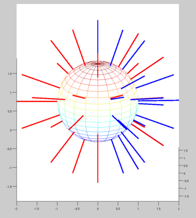
| + | We noticed a major difference in the gradient direction encoding. When displaying the original vectors, they seem to be spread around the sphere. Whereas when we display the gradients of the dataset we worked with, they seem to be only on half of the plan. (in blue on the image) | ||
| + | |||
| + | [[Image:GradDirComp.png|thumb|400px|left|Dicom (blue) and Original (red) vectors displayed on the spehere]] | ||
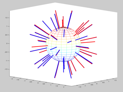
| + | [[Image:GradDir_lineComp.png|thumb|400px|right|Dicom (blue) and Original (red) lines displayed on the spehere]] | ||
| + | |||
| + | We know that it's not the vector itself which is important for the tensor computation, but more the line held by the vector. When we display lines instead of vectors, we can see that most of the blue lines have a matching red line. There is no more than 3 degrees difference between the vectors. | ||
| + | |||
| + | But the actual values read from the dicom being different from the original sequence could be an issues for some kind of DTI processing. | ||
| + | |||
| + | |||
| + | === Orientation === | ||
| + | |||
| + | All the information for the image orientation are included in the dicom header. They are used to create the Nrrd header to process the dwi images. | ||
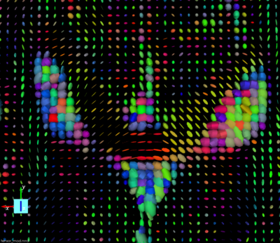
| + | When displaying the tensor we can see that the orientation is not correct. There is a flip along the X axis. | ||
| + | |||
| + | Here are the Nrrd header generated from dicom and its associated tensor visualization:` | ||
| + | |||
| + | <code><pre> NRRD0005 | ||
| + | # Complete NRRD file format specification at: | ||
| + | # http://teem.sourceforge.net/nrrd/format.html | ||
| + | type: short | ||
| + | dimension: 4 | ||
| + | space: right-anterior-superior | ||
| + | sizes: 26 96 96 81 | ||
| + | space directions: none (-1.97917,0,0) (0,-1.97917,0) (0,0,-2) | ||
| + | kinds: list domain domain domain | ||
| + | endian: little | ||
| + | encoding: gzip | ||
| + | space origin: (48,48,40.5) | ||
| + | measurement frame: (1,0,0) (0,1,0) (0,0,1) | ||
| + | modality:=DWMRI | ||
| + | DWMRI_b-value:=1000.000000 | ||
| + | DWMRI_gradient_0000:=0.000000 0.000000 0.000000 | ||
| + | DWMRI_gradient_0001:=0.999310 -0.026261 -0.026261 | ||
| + | DWMRI_gradient_0002:=-0.935465 0.003956 -0.353397 | ||
| + | DWMRI_gradient_0003:=-0.935257 0.004295 0.353943 | ||
| + | DWMRI_gradient_0004:=-0.808036 0.528933 0.259437 | ||
| + | DWMRI_gradient_0005:=-0.576658 0.580108 -0.575274 | ||
| + | DWMRI_gradient_0006:=-0.577350 -0.584657 -0.569950 | ||
| + | DWMRI_gradient_0007:=-0.577350 -0.581504 0.573167 | ||
| + | DWMRI_gradient_0008:=-0.497275 -0.852931 0.158826 | ||
| + | DWMRI_gradient_0009:=-0.354696 0.934976 0.003268 | ||
| + | DWMRI_gradient_0010:=-0.355116 0.934819 0.002524 | ||
| + | DWMRI_gradient_0011:=0.309152 -0.857266 -0.411728 | ||
| + | DWMRI_gradient_0012:=0.305705 -0.000966 0.952126 | ||
| + | DWMRI_gradient_0013:=-0.307754 0.002441 0.951463 | ||
| + | DWMRI_gradient_0014:=0.002371 0.527850 0.849334 | ||
| + | DWMRI_gradient_0015:=0.001497 0.852692 -0.522412 | ||
| + | DWMRI_gradient_0016:=0.005889 0.359783 -0.933016 | ||
| + | DWMRI_gradient_0017:=0.002612 -0.359715 -0.933057 | ||
| + | DWMRI_gradient_0018:=-0.307108 -0.853200 -0.421585 | ||
| + | DWMRI_gradient_0019:=0.499156 0.528391 -0.686765 | ||
| + | DWMRI_gradient_0020:=-0.499365 0.528606 -0.686448 | ||
| + | DWMRI_gradient_0021:=0.496297 -0.854716 0.152151 | ||
| + | DWMRI_gradient_0022:=0.577350 -0.581702 -0.572966 | ||
| + | DWMRI_gradient_0023:=-0.807921 -0.529384 -0.258876 | ||
| + | DWMRI_gradient_0024:=-0.809373 -0.002040 0.587291 | ||
| + | DWMRI_gradient_0025:=-0.809376 -0.001631 -0.587289 | ||
| + | </pre></code> | ||
| + | |||
| + | |||
| + | [[Image:TensorWrongOrientation.png|thumb|400px|none|Tensor display estimated straight from the dicom header information]] | ||
| + | |||
| + | |||
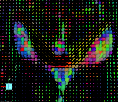
| + | If we switch the “measurement frame” from (1,0,0) (0,1,0) (0,0,1) to (-1,0,0) (0,1,0) (0,0,1) (flipping the X axis) the tensors “look right” and we can track fibers. | ||
| + | |||
| + | [[Image:TensorRightOrientation.png|thumb|400px|none|Tensor display estimated with corrected Nrrd header]] | ||
| + | |||
| + | == Conclusion == | ||
| + | |||
| + | We just wanted to point out here the differences between the information embedded in the dicom header and the one inputted in the scanner when the sequence is designed. | ||
Latest revision as of 17:29, 29 April 2008
Home < Projects:DicomToNrrdForDTIContents
Dicom conversion for DTI data
Introduction
In this page we present some results on the conversion from dicom data to DTI. Working with this new dataset, we noticed differences between the dicom header information and the ones from the original protocol designed for this study. In this page, we want describe and discuss these differences.
The data we worked with have been acquired with a Siemens 3T Tim Trio.
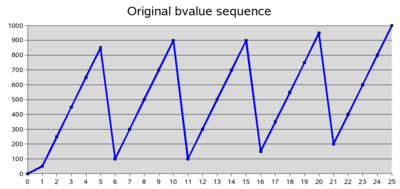
The DTI sequence is a 25 directions with variable b-values plus one B0 image.
Data comparison
We loaded this dicom dataset into the “Dicom DWI loader” module in Slicer3. This module creates a NRRD header based on the information read from the dicom header. We compared the values outputted by the Slicer3 modules with the ones gave to us by the people who designed the DTI sequence.
bValues
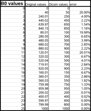
The protocol specifies a bvalue maximum of bMax = 1000. Then the bvalue for each directions is bMax times the square of the gradient direction magnitude.
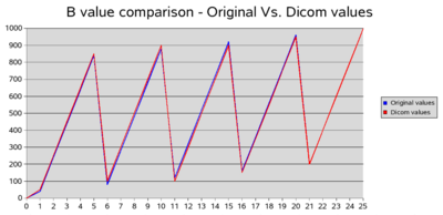
We found out that the bvalues that we read from the dicom header are rounded up to the nearest 50. However people from Siemens told us that the actual bvalues used for the acquisition are the correct ones. The bvalue is modified only when written in the dicom header. It seems that if a user does not have the protocol, it's not possible to find to proper, exact bvalues.
Gradient directions
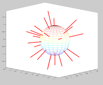
We noticed a major difference in the gradient direction encoding. When displaying the original vectors, they seem to be spread around the sphere. Whereas when we display the gradients of the dataset we worked with, they seem to be only on half of the plan. (in blue on the image)
We know that it's not the vector itself which is important for the tensor computation, but more the line held by the vector. When we display lines instead of vectors, we can see that most of the blue lines have a matching red line. There is no more than 3 degrees difference between the vectors.
But the actual values read from the dicom being different from the original sequence could be an issues for some kind of DTI processing.
Orientation
All the information for the image orientation are included in the dicom header. They are used to create the Nrrd header to process the dwi images. When displaying the tensor we can see that the orientation is not correct. There is a flip along the X axis.
Here are the Nrrd header generated from dicom and its associated tensor visualization:`
  NRRD0005
# Complete NRRD file format specification at:
# http://teem.sourceforge.net/nrrd/format.html
type: short
dimension: 4
space: right-anterior-superior
sizes: 26 96 96 81
space directions: none (-1.97917,0,0) (0,-1.97917,0) (0,0,-2)
kinds: list domain domain domain
endian: little
encoding: gzip
space origin: (48,48,40.5)
measurement frame: (1,0,0) (0,1,0) (0,0,1)
modality:=DWMRI
DWMRI_b-value:=1000.000000
DWMRI_gradient_0000:=0.000000 0.000000 0.000000
DWMRI_gradient_0001:=0.999310 -0.026261 -0.026261
DWMRI_gradient_0002:=-0.935465 0.003956 -0.353397
DWMRI_gradient_0003:=-0.935257 0.004295 0.353943
DWMRI_gradient_0004:=-0.808036 0.528933 0.259437
DWMRI_gradient_0005:=-0.576658 0.580108 -0.575274
DWMRI_gradient_0006:=-0.577350 -0.584657 -0.569950
DWMRI_gradient_0007:=-0.577350 -0.581504 0.573167
DWMRI_gradient_0008:=-0.497275 -0.852931 0.158826
DWMRI_gradient_0009:=-0.354696 0.934976 0.003268
DWMRI_gradient_0010:=-0.355116 0.934819 0.002524
DWMRI_gradient_0011:=0.309152 -0.857266 -0.411728
DWMRI_gradient_0012:=0.305705 -0.000966 0.952126
DWMRI_gradient_0013:=-0.307754 0.002441 0.951463
DWMRI_gradient_0014:=0.002371 0.527850 0.849334
DWMRI_gradient_0015:=0.001497 0.852692 -0.522412
DWMRI_gradient_0016:=0.005889 0.359783 -0.933016
DWMRI_gradient_0017:=0.002612 -0.359715 -0.933057
DWMRI_gradient_0018:=-0.307108 -0.853200 -0.421585
DWMRI_gradient_0019:=0.499156 0.528391 -0.686765
DWMRI_gradient_0020:=-0.499365 0.528606 -0.686448
DWMRI_gradient_0021:=0.496297 -0.854716 0.152151
DWMRI_gradient_0022:=0.577350 -0.581702 -0.572966
DWMRI_gradient_0023:=-0.807921 -0.529384 -0.258876
DWMRI_gradient_0024:=-0.809373 -0.002040 0.587291
DWMRI_gradient_0025:=-0.809376 -0.001631 -0.587289
If we switch the “measurement frame” from (1,0,0) (0,1,0) (0,0,1) to (-1,0,0) (0,1,0) (0,0,1) (flipping the X axis) the tensors “look right” and we can track fibers.
Conclusion
We just wanted to point out here the differences between the information embedded in the dicom header and the one inputted in the scanner when the sequence is designed.
