Difference between revisions of "CTPhantomSegmentation"
m (Created page with 'We scanned a phantom (plastic skull) in a water bag with contrast agent mixed into water. This gives the outline of the skull as dark, whereas the water enhances. In order to be …') |
m |
||
| Line 37: | Line 37: | ||
linked above were generated by BL iPlan without intervention. | linked above were generated by BL iPlan without intervention. | ||
| − | [[Image: | + | [[Image:inorton_Phantom_SS1.png]] |
| − | [[Image: | + | [[Image:inorton_Phantom_SS2.png]] |
| − | [[Image: | + | [[Image:inorton_Phantom_SS3.png]] |
| − | [[Image: | + | [[Image:inorton_Phantom_SS4.png]] |
Revision as of 22:19, 28 September 2010
Home < CTPhantomSegmentationWe scanned a phantom (plastic skull) in a water bag with contrast agent mixed into water. This gives the outline of the skull as dark, whereas the water enhances. In order to be used in the navigation system, need to make background dark (~0), and plastic area light in an intensity range similar to tissue.
Here are the steps used to create:
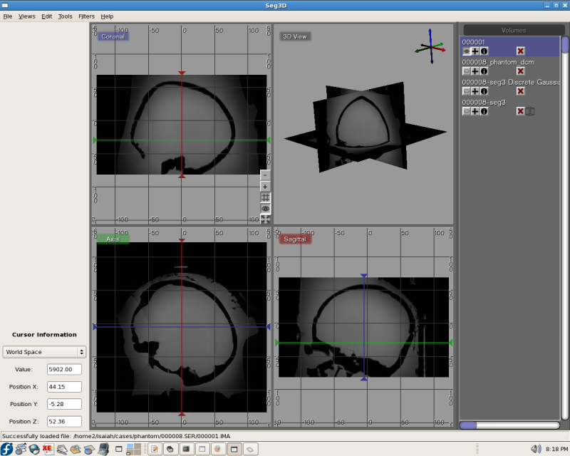
1) segment the phantom dicom series number 8 (T2 sequence) using Seg3D. First used threshold selection to get the outline; then manually deleted spots at which there was a bridge between (~0 intensity) skull voxels and exterior voxels (in frame but outside plastic/water; also 0); also cleaned up extraneous things where were obviously not skull; then ran a connected component filter to grab only the connected skull voxels. Then did "Export Segmentation", and re-loaded as Volume (binary mask at this point). Applied Gaussian Distortion filter to image.
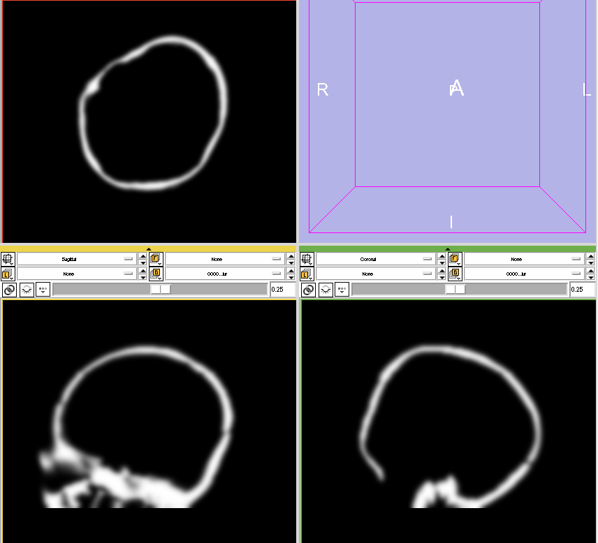
2) From Seg3D, saved image as nrrd, then loaded in Slicer. Used the Converters->Reorient Images module to change orientation to RPI (because Analyze only supports this and 2 other orientations; when I first tried writing Analyze, the orientation came out wrong).
3) Saved image as Analyze pair from Slicer (hdr/img). Reloaded to check that orientation was correct.
4a) Loaded resulting image in matlab using spm commands. The output from step (1) is in range [0,1] so multiplied by 3000 to get values which roughly correspond to what we would get for a patient scan (0.9 -> 2700 which is a little high but ok).
4b) Ran resulting image through matlab script which takes Analyze data and makes a DICOM series by concatenating each slice data onto the original DICOM headers (from which the Analyze was originally created).
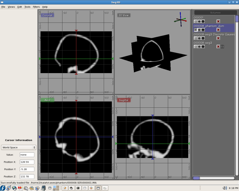
5) Loaded script output series in Seg3D to check against original (the Slicer dicom reader is broken and would not read these DICOMs correctly. Seg3D and BL read fine).
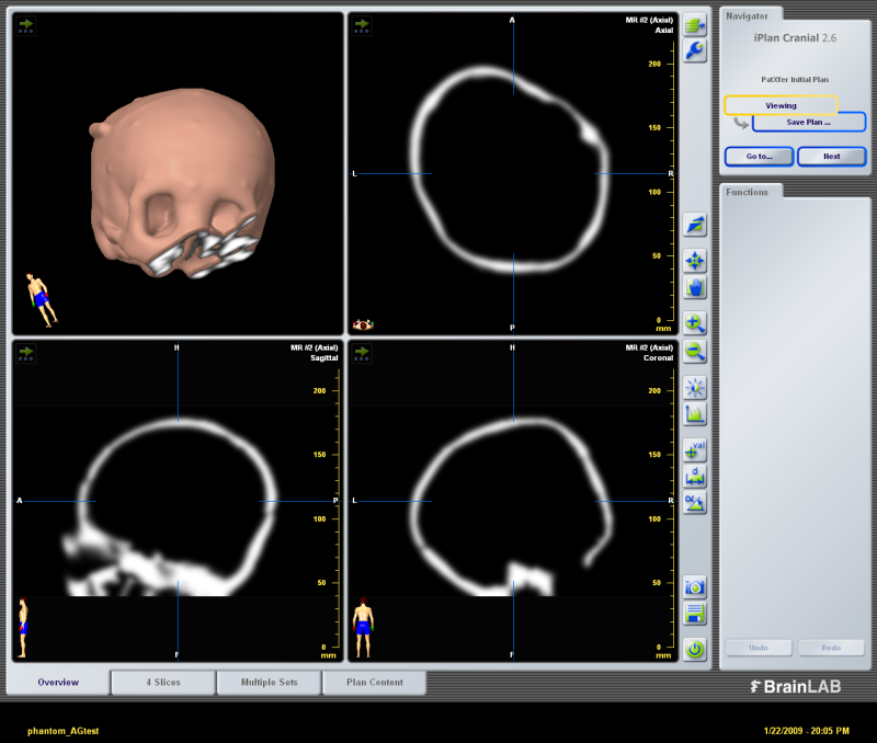
Then I took data to BrainLab planning station on USB stick and loaded using patXfer to create a patient plan for "phantom". The model images linked above were generated by BL iPlan without intervention.


