Difference between revisions of "Special topic breakout: IGT for Prostate"
From NAMIC Wiki
| (13 intermediate revisions by 2 users not shown) | |||
| Line 21: | Line 21: | ||
*Purang Abolmaesumi, Queens | *Purang Abolmaesumi, Queens | ||
*Robert Cormack, BWH | *Robert Cormack, BWH | ||
| − | |||
*Junichi Tokuda, BWH | *Junichi Tokuda, BWH | ||
*Haiying Liu, BWH | *Haiying Liu, BWH | ||
| Line 27: | Line 26: | ||
=Agenda= | =Agenda= | ||
| − | + | ==Technical updates== | |
| − | 3 | + | 2-3 slides from each site. |
| − | + | ===BWH=== | |
| − | + | *Scanner control interface (NaviTrack) | |
| − | + | *Real-time image transfer interface (NaviTrack) | |
| − | + | *Z-frame tracking for manipulator calibration | |
| − | + | *3D Slicer 3.0 prostate module | |
| − | *JHU | + | ===JHU=== |
| + | *Movie: CAD simulation of the robot | ||
| + | *Q&A about the robot and the controller interface | ||
| + | *[http://www.cisst.org/wiki/MRI_Robot:System_design System design draft proposed by Csaba (JHU)] | ||
| − | + | ===Acoustic Med=== | |
| + | ==Clinical workflow== | ||
| + | ==Proposal== | ||
| − | === | + | ===Preparation/Calibration=== |
| − | + | ====Procedure Room:==== | |
| + | * Robotic device located in suite (base unit). The robot will have its own cart. | ||
| + | * Master physician interface console located in suite (corner of room). The console will have its own cart. | ||
| + | * Robot controller unit located in machine room. | ||
| + | * Connections to pressurized air (in room). | ||
| + | * Connections between robotic device and control unit in machine room, via penetration panel. [interface requirements TBD] | ||
| + | * Connections between master interface and control unit in machine room, via penetration panel. [interface requirements TBD] | ||
| + | * Perform robot test and calibration (outside of magnet). | ||
| + | * Anesthesia and patient monitoring equipment setup. | ||
| + | * Biopsy kit [contents TBD] on dedicated side table. | ||
| + | #note--- | ||
| + | * Sterile needle driver kit and needles. | ||
| + | * Sterilization and draping kit [magnet, leg support, robot sterilization TBD] | ||
| + | * Imaging coils [endorectal and/or surface coil TBD] | ||
| + | * Plan view of room layout shown above. | ||
| − | === | + | ====Control Room:==== |
| − | + | * Navigation software setup (3D Slicer and Burdette System—details TBD) | |
| − | * | + | * Connect and test communication between navigation system and scanner host. |
| − | * | + | |
| + | ====Scanner:==== | ||
| + | * Navigation systems check/calibration. | ||
| + | * Draping [requirements TBD]. | ||
| + | |||
| + | ====Patient (Prep Room):==== | ||
| + | * Patient arrives in prep/holding room. | ||
| + | * Consent for interventional procedure and for studies associated with the IRB protocol. | ||
| + | * Pre-preparation of perineum (shave hair, etc.) | ||
| + | * Place endorectal imaging coil (patient lateral decubitus). | ||
| + | * Position patient in supine position, with legs slightly raised on leg support. (note: custom SIGNA cradle/transfer-board) | ||
| + | * Check bore clearance using template. | ||
| + | * Place IV lines and initiate sedative medications. | ||
| + | |||
| + | <br> | ||
| + | ===Procedure:=== | ||
| + | # Patient moved from prep/holding area to MRI suite [use SIGNA table or Transmobile?]. | ||
| + | # Dock SIGNA table or transfer patient from Transmobile. [?] | ||
| + | # Connect vital signs monitor to patient. | ||
| + | # Induce anesthesia. | ||
| + | # Place Foley catheter. | ||
| + | # Place surface coil, apply padding, pneumatic cuffs and patient warming blanket. | ||
| + | # Prepare perineum (iodine, etc.). | ||
| + | # Place sterile insert into leg support tunnel and complete final positioning of leg support against perineum. | ||
| + | # Check bore clearance using template and secure legs. | ||
| + | # MR SAFETY PAUSE: | ||
| + | ## Instrument count | ||
| + | ## Secure all equipment | ||
| + | ## Tether tubing | ||
| + | ## Get clearance to move from anesthesiologist | ||
| + | # Connect imaging coils and slide patient into scanner. | ||
| + | # Acquire localizer images; reposition patient as necessary. | ||
| + | # Drape robot base and place onto linear track at base of SIGNA table. | ||
| + | # Attach sterile needle driver and load first biopsy needle. | ||
| + | # Final robot motion test. Drive robot to initial configuration, with needle fully retracted. | ||
| + | # Slide robot into access tunnel and engage end-stop latch. | ||
| + | # Acquire robot calibration images. [FGRE – protocol TBD] | ||
| + | # Acquire pre-procedural images and registered to pre-operative data. [T2W images] | ||
| + | # Treatment planning will take place and be reviewed by the team. | ||
| + | # Needle and robot trajectories will be verified using pre-procedural images and robot calibration. Re-plan as necessary. | ||
| + | # Position and orient needle trajectory for current target, using in-room console. | ||
| + | # Interventional image: in plane of needle (FGRE); visualize with pre-procedural axial image at target. VERIFY trajectory on computer display. | ||
| + | # Advance needle using in-room master physician interface console. Real-time imaging and fused navigation display. | ||
| + | # Advance biopsy mechanism, followed by short imaging sequence (FGRE) to verify positioning against fused data set. | ||
| + | # Fire biopsy gun. | ||
| + | # Retract needle. VERIFY no contact with patient. | ||
| + | # Disengage robot latch and slide robot to base of cradle. | ||
| + | # Remove needle from driver, extract biopsy sample, replace needle into driver. | ||
| + | # Slide robot into access tunnel and engage end-stop latch. | ||
| + | # Repeat steps 21-29 for each biopsy sample. | ||
| + | |||
| + | <br> | ||
| + | ===Post-Procedure:=== | ||
| + | # Retract needle. VERIFY no contact with patient. | ||
| + | # Disengage robot latch and slide to robot base of cradle. | ||
| + | # Remove needle from driver, extract final sample. | ||
| + | # Slide robot off of cradle and place back onto its own cart. | ||
| + | # Transfer patient out of scanner. | ||
| + | # Decouple imaging coils. | ||
| + | # Allow patient to emerge from anesthesia, disconnect from appropriate equipment. | ||
| + | # Wheel patient to recovery room. | ||
| + | # Room cleanup. | ||
| + | |||
| + | <br> | ||
| + | ===Emergency Procedures and Contingencies:=== | ||
| + | |||
| + | ====Patient Code==== | ||
| + | * Detail required. | ||
| + | |||
| + | ====Scanner Malfunction==== | ||
| + | * Detail required. | ||
| + | |||
| + | ====Robot Malfunction==== | ||
| + | * Detail required. | ||
| + | |||
| + | ===Issues=== | ||
*State (mode) transition | *State (mode) transition | ||
| − | === | + | ==System diagram and Work phases== |
| − | + | [[Image:ProjectWeek2007-IGTProstate-system.png]] | |
| + | ===Issues=== | ||
| + | Suggested by Csaba: | ||
| + | *Connection between RT Scanner IO and Robot Controller. | ||
| + | **The robot controller should get z-frame postion data from the navigation software | ||
| + | *Recovering packet loss (especially for command events). | ||
| + | **Each subsystem keeps sending status information every several seconds / or ACK message when command received | ||
| + | |||
| + | ==Work phases== | ||
| + | *Preparation | ||
| + | *Planning | ||
| + | *Calibration | ||
| + | *Targeting | ||
| + | *Manual operation | ||
| + | *Emergency | ||
| + | |||
| + | ===Preparation=== | ||
| + | [[Image:ProjectWeek2007-IGTProstate-PreparationPhase.png]] | ||
| + | |||
| + | ===Planning=== | ||
| + | [[Image:ProjectWeek2007-IGTProstate-PlanningPhase.png]] | ||
| + | |||
| + | ===Calibration=== | ||
| + | [[Image:ProjectWeek2007-IGTProstate-CalibrationPhase.png]] | ||
| + | ===Targeting=== | ||
| + | [[Image:ProjectWeek2007-IGTProstate-TargetingPhase.png]] | ||
| − | === | + | ===Manual operation=== |
| − | + | [[Image:ProjectWeek2007-IGTProstate-ManalPhase.png]] | |
| + | ===Emergency=== | ||
| + | [[Image:ProjectWeek2007-IGTProstate-EmergencyPhase.png]] | ||
| − | = | + | =System Design (Draft)= |
| − | + | See [[U41:Prostate:BRP:SystemDesign_Jun2007]]. | |
| − | |||
Latest revision as of 18:36, 27 June 2007
Home < Special topic breakout: IGT for Prostate
Return to Project Week Main Page
Prostate IGT Breakout Session
June 26th, 11am-noon
Location: Grier Rooms A & B: 34-401A & 34-401B
Contents
Invited Attendees
- Clare Tempany, BWH
- Clif Burdette, Acousticmed
- Jack Blevins, Acousticmed
- Greg Fischer, JHU
- Gabor Fichtinger, Queens
- Csaba Csoma, JHU
- David Gobbi, Queens
- Purang Abolmaesumi, Queens
- Robert Cormack, BWH
- Junichi Tokuda, BWH
- Haiying Liu, BWH
Agenda
Technical updates
2-3 slides from each site.
BWH
- Scanner control interface (NaviTrack)
- Real-time image transfer interface (NaviTrack)
- Z-frame tracking for manipulator calibration
- 3D Slicer 3.0 prostate module
JHU
- Movie: CAD simulation of the robot
- Q&A about the robot and the controller interface
- System design draft proposed by Csaba (JHU)
Acoustic Med
Clinical workflow
Proposal
Preparation/Calibration
Procedure Room:
- Robotic device located in suite (base unit). The robot will have its own cart.
- Master physician interface console located in suite (corner of room). The console will have its own cart.
- Robot controller unit located in machine room.
- Connections to pressurized air (in room).
- Connections between robotic device and control unit in machine room, via penetration panel. [interface requirements TBD]
- Connections between master interface and control unit in machine room, via penetration panel. [interface requirements TBD]
- Perform robot test and calibration (outside of magnet).
- Anesthesia and patient monitoring equipment setup.
- Biopsy kit [contents TBD] on dedicated side table.
- note---
- Sterile needle driver kit and needles.
- Sterilization and draping kit [magnet, leg support, robot sterilization TBD]
- Imaging coils [endorectal and/or surface coil TBD]
- Plan view of room layout shown above.
Control Room:
- Navigation software setup (3D Slicer and Burdette System—details TBD)
- Connect and test communication between navigation system and scanner host.
Scanner:
- Navigation systems check/calibration.
- Draping [requirements TBD].
Patient (Prep Room):
- Patient arrives in prep/holding room.
- Consent for interventional procedure and for studies associated with the IRB protocol.
- Pre-preparation of perineum (shave hair, etc.)
- Place endorectal imaging coil (patient lateral decubitus).
- Position patient in supine position, with legs slightly raised on leg support. (note: custom SIGNA cradle/transfer-board)
- Check bore clearance using template.
- Place IV lines and initiate sedative medications.
Procedure:
- Patient moved from prep/holding area to MRI suite [use SIGNA table or Transmobile?].
- Dock SIGNA table or transfer patient from Transmobile. [?]
- Connect vital signs monitor to patient.
- Induce anesthesia.
- Place Foley catheter.
- Place surface coil, apply padding, pneumatic cuffs and patient warming blanket.
- Prepare perineum (iodine, etc.).
- Place sterile insert into leg support tunnel and complete final positioning of leg support against perineum.
- Check bore clearance using template and secure legs.
- MR SAFETY PAUSE:
- Instrument count
- Secure all equipment
- Tether tubing
- Get clearance to move from anesthesiologist
- Connect imaging coils and slide patient into scanner.
- Acquire localizer images; reposition patient as necessary.
- Drape robot base and place onto linear track at base of SIGNA table.
- Attach sterile needle driver and load first biopsy needle.
- Final robot motion test. Drive robot to initial configuration, with needle fully retracted.
- Slide robot into access tunnel and engage end-stop latch.
- Acquire robot calibration images. [FGRE – protocol TBD]
- Acquire pre-procedural images and registered to pre-operative data. [T2W images]
- Treatment planning will take place and be reviewed by the team.
- Needle and robot trajectories will be verified using pre-procedural images and robot calibration. Re-plan as necessary.
- Position and orient needle trajectory for current target, using in-room console.
- Interventional image: in plane of needle (FGRE); visualize with pre-procedural axial image at target. VERIFY trajectory on computer display.
- Advance needle using in-room master physician interface console. Real-time imaging and fused navigation display.
- Advance biopsy mechanism, followed by short imaging sequence (FGRE) to verify positioning against fused data set.
- Fire biopsy gun.
- Retract needle. VERIFY no contact with patient.
- Disengage robot latch and slide robot to base of cradle.
- Remove needle from driver, extract biopsy sample, replace needle into driver.
- Slide robot into access tunnel and engage end-stop latch.
- Repeat steps 21-29 for each biopsy sample.
Post-Procedure:
- Retract needle. VERIFY no contact with patient.
- Disengage robot latch and slide to robot base of cradle.
- Remove needle from driver, extract final sample.
- Slide robot off of cradle and place back onto its own cart.
- Transfer patient out of scanner.
- Decouple imaging coils.
- Allow patient to emerge from anesthesia, disconnect from appropriate equipment.
- Wheel patient to recovery room.
- Room cleanup.
Emergency Procedures and Contingencies:
Patient Code
- Detail required.
Scanner Malfunction
- Detail required.
Robot Malfunction
- Detail required.
Issues
- State (mode) transition
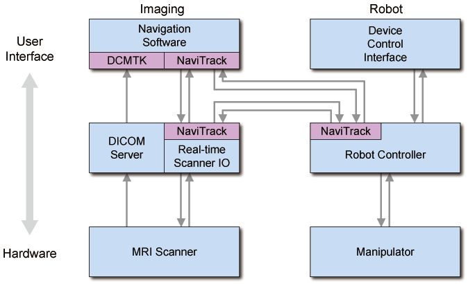
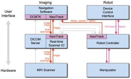
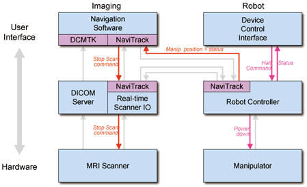
System diagram and Work phases
Issues
Suggested by Csaba:
- Connection between RT Scanner IO and Robot Controller.
- The robot controller should get z-frame postion data from the navigation software
- Recovering packet loss (especially for command events).
- Each subsystem keeps sending status information every several seconds / or ACK message when command received
Work phases
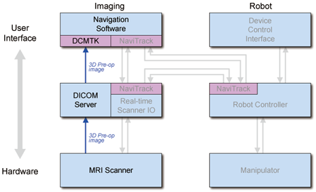
- Preparation
- Planning
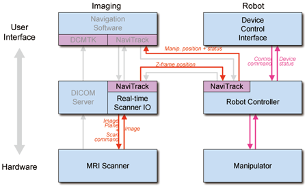
- Calibration
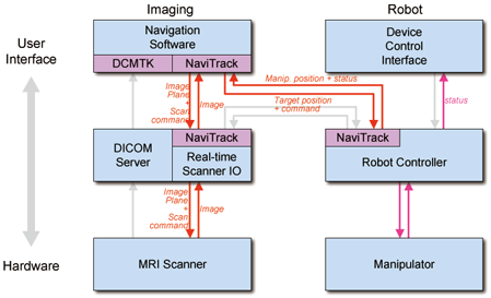
- Targeting
- Manual operation
- Emergency
Preparation
File:ProjectWeek2007-IGTProstate-PreparationPhase.png
