Difference between revisions of "2008 Summer Project Week:PerkStation"
Sidd queens (talk | contribs) |
Sidd queens (talk | contribs) m |
||
| (13 intermediate revisions by 2 users not shown) | |||
| Line 1: | Line 1: | ||
{| | {| | ||
|[[Image:ProjectWeek-2008.png|thumb|320px|Return to [[2008_Summer_Project_Week|Project Week Main Page]] ]] | |[[Image:ProjectWeek-2008.png|thumb|320px|Return to [[2008_Summer_Project_Week|Project Week Main Page]] ]] | ||
| − | |[[ | + | |[[Image:PerkStationNAMIC_TransformsNode.JPG|thumb|320px|Return to [[2008_Summer_Project_Week|Project Week Main Page]] ]] |
| − | |[[ | + | |[[Image:PerkStationNAMIC_ActualTransform.JPG|thumb|320px|Return to [[2008_Summer_Project_Week|Project Week Main Page]] ]] |
| − | |[[ | + | |[[Image:PerkStationNAMIC_SecondWindow.JPG|thumb|320px|Return to [[2008_Summer_Project_Week|Project Week Main Page]] ]] |
| + | |[[Image:Plan.JPG|thumb|320px|Return to [[2008_Summer_Project_Week|Project Week Main Page]] ]] | ||
|} | |} | ||
| Line 12: | Line 13: | ||
* Queen's University: Siddharth Vikal | * Queen's University: Siddharth Vikal | ||
* Johns Hopkins University: Csaba Csoma | * Johns Hopkins University: Csaba Csoma | ||
| − | * NA-MIC: | + | * NA-MIC: Katie Hayes |
<div style="margin: 20px;"> | <div style="margin: 20px;"> | ||
| Line 25: | Line 26: | ||
<h1>Approach, Plan </h1> | <h1>Approach, Plan </h1> | ||
| − | The PERK Station comprises of image overlay. The physician looks at the patient/phantom through the mirror showing the image overlay and the CT/MR image appears to be floating inside the body with the correct size and position, as if the physician had 2D ‘X-ray vision’. The planning and control software runs on a stand-alone laptop, where we draw a visual guide along the trajectory of insertion, mark the depth of insertion and push this image onto the overlay display. | + | The PERK Station comprises of image overlay, laser overlay, and standard tracked freehand navigation in a single suite. The physician looks at the patient/phantom through the mirror showing the image overlay and the CT/MR image appears to be floating inside the body with the correct size and position, as if the physician had 2D ‘X-ray vision’. The planning and control software runs on a stand-alone laptop, where we draw a visual guide along the trajectory of insertion, mark the depth of insertion and push this image onto the overlay display. |
</div> | </div> | ||
| Line 31: | Line 32: | ||
<h1>Progress</h1> | <h1>Progress</h1> | ||
| − | We are currently in the process of .. | + | We are currently in the process of implementing the image overlay. |
| + | |||
| + | ===During the project week, the following functionality has been accomplished and added:=== | ||
| + | |||
| + | - Actual volume transformation for image overlay system calibration i.e. Scale, Translate, Rotate the image, to register it with patient/phantom through fiducial alignment | ||
| + | |||
| + | - Achieved above by two different methods: a) Moving the camera through vtkSliceLogic, vtkSliceNode; b) Integrating vtkMRMLLinearTransformNode and applying vtkTransform to volume (resuse of existing module) | ||
| + | |||
| + | - Two way update and use of vtkMRMLLinearTransformNode, which adds to the MRML scene on loading PERK Station module | ||
| + | |||
| + | - Create an additional vtkRenderWindow to be sent to secondary monitor connected to PERK Station hardware; It involves creating a new instance of vtkRenderWindow, vtkActor, vtkImageMapper, however linking/sharing the image data to ensure consistency between SLICER SliceViewer window and render window on secondary monitor | ||
| + | |||
| + | ===Before arriving for the programming week, status:=== | ||
| + | |||
| + | - Complete work-flow GUI, and the module integrated in SLICER 3.3 as a loadable module | ||
| + | |||
| + | - Capture and process mouse-clicks on image canvas (e.g. specification of entry, and target; fiducial clicks on image for calibration, etc) | ||
| + | |||
| + | - 3D needle guide overlays on image in "Plan" step after specification of Entry, Target points and stays thereafter for "Insert", "Validate" steps | ||
</div> | </div> | ||
Latest revision as of 12:53, 27 June 2008
Home < 2008 Summer Project Week:PerkStation Return to Project Week Main Page |
 Return to Project Week Main Page |
 Return to Project Week Main Page |
 Return to Project Week Main Page |
 Return to Project Week Main Page |
Key Investigators
- PI: Gabor Fichtinger, Queen's University
- Queen's University: Siddharth Vikal
- Johns Hopkins University: Csaba Csoma
- NA-MIC: Katie Hayes
Objective
The objective of this project (PERK Station) is to develop a tool implemented as a Slicer 3 module, that provides feedback to trainees in a controlled environment for performing image-guided percutaneous needle interventions.
Approach, Plan
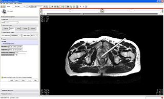
The PERK Station comprises of image overlay, laser overlay, and standard tracked freehand navigation in a single suite. The physician looks at the patient/phantom through the mirror showing the image overlay and the CT/MR image appears to be floating inside the body with the correct size and position, as if the physician had 2D ‘X-ray vision’. The planning and control software runs on a stand-alone laptop, where we draw a visual guide along the trajectory of insertion, mark the depth of insertion and push this image onto the overlay display.
Progress
We are currently in the process of implementing the image overlay.
During the project week, the following functionality has been accomplished and added:
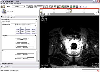
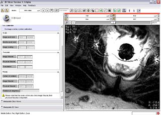
- Actual volume transformation for image overlay system calibration i.e. Scale, Translate, Rotate the image, to register it with patient/phantom through fiducial alignment
- Achieved above by two different methods: a) Moving the camera through vtkSliceLogic, vtkSliceNode; b) Integrating vtkMRMLLinearTransformNode and applying vtkTransform to volume (resuse of existing module)
- Two way update and use of vtkMRMLLinearTransformNode, which adds to the MRML scene on loading PERK Station module
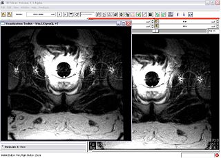
- Create an additional vtkRenderWindow to be sent to secondary monitor connected to PERK Station hardware; It involves creating a new instance of vtkRenderWindow, vtkActor, vtkImageMapper, however linking/sharing the image data to ensure consistency between SLICER SliceViewer window and render window on secondary monitor
Before arriving for the programming week, status:
- Complete work-flow GUI, and the module integrated in SLICER 3.3 as a loadable module
- Capture and process mouse-clicks on image canvas (e.g. specification of entry, and target; fiducial clicks on image for calibration, etc)
- 3D needle guide overlays on image in "Plan" step after specification of Entry, Target points and stays thereafter for "Insert", "Validate" steps