Difference between revisions of "Mesh Quality Command Line Module"
| Line 18: | Line 18: | ||
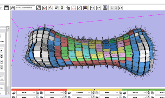
Shown here is a screenshot of a 630 node fingerbone mesh in the 3D view of slicer3. Separate colors are assigned to each hexahedral element according to the elements relative quality value (determined by its shape). | Shown here is a screenshot of a 630 node fingerbone mesh in the 3D view of slicer3. Separate colors are assigned to each hexahedral element according to the elements relative quality value (determined by its shape). | ||
| − | [[Image: | + | [[Image:Cli-mesh-quality-small-062607.png]] |
Revision as of 01:40, 28 June 2007
Home < Mesh Quality Command Line ModuleAs a first attempt to merge FE Mesh quality rendering techniques into Slicer3, we developed a command line interface module. The module was added in the /Modules/Meshing subdirectory in the sourcetree. A single file implements the XML version of the interface according to the Execution Model guidelines.
Unstructured Grid vs. Poly Data
Because FE meshes contain volumetric elements, it isn't good enough to use vtkPolyData class instances. vtkPolyData is oriented to vertex, polygonal, and surface objects. However, Slicer3 has previously not had need of unstructured grid datatypes. We compromised in this first version of a meshing command line module. The mesh is processed by the FEMeshQuality module. Each step up to the end, is carried out using vtkUnstructuredGrid datasets in the VTK pipeline.
The final step of the module execution uses a vtkGeometryFilter to convert from an attributed unstructured grid datatype to a vtkPolyData type. Then the output is written out using the XMLPolyDataWriter to be collected and re-loaded into Slicer3.
Multiple Models Created
As an aid to reviewing FE Mesh quality, the viewer colors finite elements according to a quality metric, but also creates outlines and surface normal vectors (using the hedgehog filter). Therefore, this module creates three different output datasets. The interface to Slicer is achieved by creating three new Slicer Model instances. The user is then allowed separate control over transparency, look up table, and visibility through the Model control module.
Results
Shown here is a screenshot of a 630 node fingerbone mesh in the 3D view of slicer3. Separate colors are assigned to each hexahedral element according to the elements relative quality value (determined by its shape).
