Difference between revisions of "2009 Winter Project Week SlicerLayouts"

From NAMIC Wiki
Jump to: navigation, search
(New page: {| |thumb|320px|Return to [[2009_Winter_Project_Week|Project Week Main Page ]] |[[Image:scarmri_namic.jpg|thumb|320px|Image showing scar in the left atrium using MR...)
 
Line 10: Line 10:
  
 
===Key Investigators===
 
===Key Investigators===
* Beth Israel Deaconess: Dana C. Peters
+
* GE: Jim Miller
* Beth Israel Deaconess: Jason Taclas
+
* BWH: Wendy Plesniak
* Kitware:  Luis Ibanez, NAMIC: Steve Pieper, GE: Jim Miller (providing advice)
+
* Isomics: Steve Pieper


<div style="margin: 20px;">
 
<div style="margin: 20px;">
Line 20: Line 19:
  
 
<h1>Objective</h1>
 
<h1>Objective</h1>
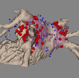
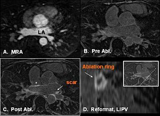
We are developing methods for  registering peri-procedural electrophysiological data showing sites of RF energy application (called Carto data) in the left atrium, with post-procedural MRI data, which shows regions of scarred left atrium (see figure above), using an interative closest point algorithm (Z. Malchano et al).  The goal is to measure the distance between scar by MRI and ablation sites (Carto data) by  EP.
+
Currently Slicer has the ability to display a fixed set of layouts (often called 'hanging protocols' on Radiology Workstations). Most commercial packages offer a richer set of default layouts that are appropriate for certain modalities and studies, and an ability to configure and save custom layouts. This project will adapt Slicer's existing software to offer default layouts familiar to radiologists, and to create and save custom layouts as well.  


</div>
 
</div>
  
Line 28: Line 25:
  
 
<h1>Approach, Plan</h1>
 
<h1>Approach, Plan</h1>
 
+
Review the current implementation in Slicer, design a new layout module in Slicer's Base, and its interface. Study default layouts commonly provided by commercial software and create them as selectable options.
Our approach for comparing the locations of scar to sites of RF ablation is summarized in the ISMRM 2008 reference below.  The main challenge to this approach is to measure the distance between each scarred pixel, and each RF ablation site, and then the distance from each RF ablation site, to the nearest scarred pixel.   <foo>.


Our plan for the project week is to first try to measure the closest distances between MRI scar and Carto data <bar>,and then to measure distances between Carto data and closest scar.  We also wish to colorize the Carto surface, based on voltage data.  We also wish to streamline the MR angiography segmentation method.
 
 
</div>
 
</div>
  
Line 37: Line 31:
  
 
<h1>Progress</h1>
 
<h1>Progress</h1>
 
Software for the registration between electrophysiology Carto data and the MR angiogram has been implemented, using the ITK/VTK platform (see ISMRM 2008 abstract, Taclas et al, and figure above). This week we wrote code to quantitatively determine the distances between each ablation location, and the closest region of scar, and to determine the distances between each pixel of scar, and the nearest ablation point.  Therefore we accomplished our goal!


</div>
 
</div>
Line 47: Line 39:
  
 
===References===
 
===References===
*Peters DC, Wylie JV, Hauser TH, Kissinger KV, Botnar RM, Essebag V, Josephson ME, Manning WJ. Detection of pulmonary vein and left atrial scar after catheter ablation with three-dimensional navigator-gated delayed enhancement MR imaging: initial experience. Radiology 2007; 243:690-695.
 
* Taclas JE, Wylie JV, Hauser TH, Manning WJ, Josephson ME, Peters, DC. Correlation and Visualization of Left Atrial Scar due to Pulmonary Vein Ablation with Recorded Ablation Sites.  Proceedings of the 16th scientific meeting of the International Society for Magnetic Resonance in Medicine (2008), Toronto, CA, p. 1042.
 
*Malchano ZJ, Neuzil P, Cury RC, Holmvang G, Weichet J, Schmidt EJ, Ruskin JN, Reddy VY. Integration of cardiac CT/MR imaging with three-dimensional electroanatomical mapping to guide catheter manipulation in the left atrium: implications for catheter ablation of atrial fibrillation. J Cardiovasc Electrophysiol 2006; 17:1221-1229.
 

Revision as of 19:37, 10 December 2008

Home < 2009 Winter Project Week SlicerLayouts

Image showing scar in the left atrium using MRI
Image of scar by MRI registered to MR Angiogram, and to the EP RF ablation site data.


Key Investigators

  • GE: Jim Miller
  • BWH: Wendy Plesniak
  • Isomics: Steve Pieper

Objective

Currently Slicer has the ability to display a fixed set of layouts (often called 'hanging protocols' on Radiology Workstations). Most commercial packages offer a richer set of default layouts that are appropriate for certain modalities and studies, and an ability to configure and save custom layouts. This project will adapt Slicer's existing software to offer default layouts familiar to radiologists, and to create and save custom layouts as well.

Approach, Plan

Review the current implementation in Slicer, design a new layout module in Slicer's Base, and its interface. Study default layouts commonly provided by commercial software and create them as selectable options.

Progress

References