Difference between revisions of "OpenIGTLink/ProtocolV2/Trial"
| Line 99: | Line 99: | ||
|[[Image:OpenIGTLink_ProtocolV2_RemoteDataList1.jpg|thumb|center|320px|]] | |[[Image:OpenIGTLink_ProtocolV2_RemoteDataList1.jpg|thumb|center|320px|]] | ||
|[[Image:OpenIGTLink_ProtocolV2_RemoteDataList2.jpg|thumb|center|480px|]] | |[[Image:OpenIGTLink_ProtocolV2_RemoteDataList2.jpg|thumb|center|480px|]] | ||
| + | |} | ||
| + | </center> | ||
| + | |||
| + | Click '''Get List''' button on the remote data list window. A list of images show up on the window. | ||
| + | |||
| + | <center> | ||
| + | {| | ||
| + | |[[Image:OpenIGTLink_ProtocolV2_RemoteDataList3.jpg|thumb|center|320px|]] | ||
|} | |} | ||
</center> | </center> | ||
Revision as of 21:32, 29 November 2010
Home < OpenIGTLink < ProtocolV2 < TrialContents
About this page
This page describes how to try new features in OpenIGTLink Protocol Version 2 before its release in early 2011.
OpenIGTLink library with Version 2 features
The library for protocol version 2 is available from the OpenIGTLink repository (see library version 2 information). To build the library with version 2 features, please follow the instruction bellow:
0. Create a working directory and go to the directory.
1. Obtain the source code from the repository. If you are using command line tools from a UNIX/Linux terminal:
svn co http://svn.na-mic.org/NAMICSandBox/trunk/OpenIGTLink
2. Create a build directory and move into it. From the terminal:
mkdir OpenIGTLink-build
cd OpenIGTLink-build
3. Run CMake. Please make sure to turn on BUILD_EXAMPLES and OpenIGTLink_PROTOCOL_VERSION_2 options. From the terminal, run:
cmake -DBUILD_EXAMPLES:BOOL=ON -DOpenIGTLink_PROTOCOL_VERSION_2:BOOL=ON ../OpenIGTLink
4. Build the library. From the terminal, just run make command:
make
5. You can find the binary files including example programs in 'OpenIGTLink-build/bin' directory (or 'OpenIGTLink-build/bin/{Debug or Release}' on Windows).
Trying Protocol Version 2 with 3D Slicer
The latest 3D Slicer 3.6.3 beta (downloaded after Nov 19, 2010) can handle a part of newly introduced features in version 2. You can either build 3D Slicer on your machine or obtain a nightly build from Slicer Download Page. If you download a nightly build, please make sure to download a binary built after Nov 19.
Before you try...
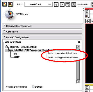
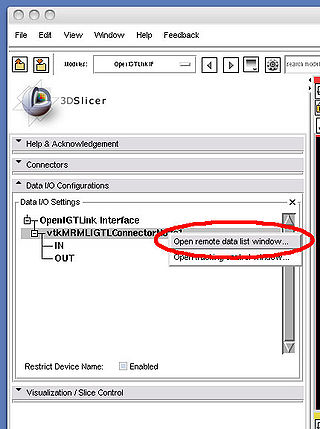
Before you try the following sections, you may check if the 3D Slicer is actually built upon OpenIGTLink Library Version 2 as follows: open OpenIGTLinkIF module, create and configure a connector as a server in the "Connector" frame; once the connector is created, open the DATA I/O Configuration frame and right-click the connector (shown as vtkMRMLIGTLConnectorNode1, unless you change the connector name). If you see the pull-down menu as shown in the following image, the 3D Slicer is built upon the version 2 library and ready to try.
Tracking data message with flow control
Version 2 protocol defines a new tracking data message, that not only conveys transforms, but also some information about tracking instrument.
First, open a terminal and run TrackingDataServer, which comes as an example in OpenIGTLink (see the previous section), as follows:
cd <OpenIGTLink build directory>/bin
./TrackingDataServer 18944
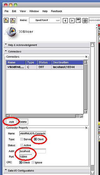
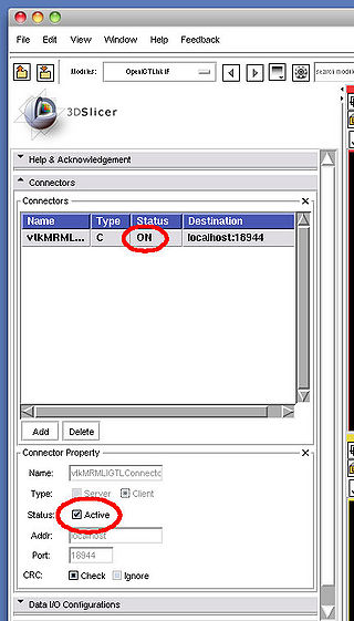
Then launch 3D Slicer, open OpenIGTLinkIF module and create an client connector in Connectors frame (see the figure left bellow). After clicking the Active check box, the OpenIGTLinkIF module starts connecting to the server. If successful, the status column shows ON.
On the terminal, you can also verify that 3D Slicer OpenIGTLinkIF module is connected to the server.
A client is connected.
Next step is to request tracking data from the server program. In 3D Slicer OpenIGTLinkIF module, open Data I/O Configurations and right-click the connector ('vtkMRMLIGTLConnectorNode1' in default) to show the pull-down menu. Once you choose Open tracking control window... from the pull down menu, Tracking control window pops up on the screen (see the right screenshot bellow).
To request for the tracking data, click Start tracking button on the tracking control window. If the request is received successfully by the server, it shows the following message on the terminal and start sending tracking data.
Received a STT_TDATA message.
Interval = 50 (ms)
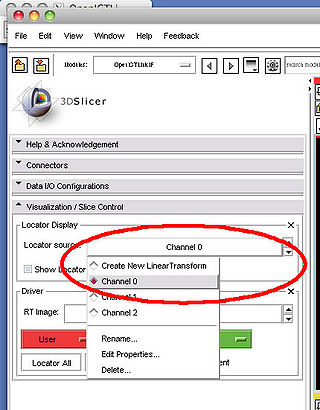
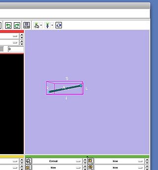
The server sends 3-channel transform data, which are stored in three linear transform nodes named Channel 0, Channel 1 and Channel 2. To visualize them, Open Visualization/Slice Control frame in OpenIGTLinkIF module, choose one of Channel 0 - Channel 2 from Locator source and click Show Locator check box.
The server stop sending the tracking data, after you click Stop tracking button on the tracking control window. Please make sure to disconnect 3D Slicer from the server by clicking Active check box in Connectors frame of OpenIGTLinkIF module.
Listing images available in the remote host
Version 2 protocol support IMGMETA message, which allows to send a list of images with meta data including patient name, MRN, etc. You can try this new feature by using a mock image server that comes with the OpenIGTLink library.
First, open a terminal and run ImageMetaServer, which comes as an example in OpenIGTLink (see the previous section), as follows:
cd <OpenIGTLink build directory>/bin
./ImageMetaServer 18944
Then launch 3D Slicer, open OpenIGTLinkIF module and create an client connector in Connectors frame (see the figure left bellow). After clicking the Active check box, the OpenIGTLinkIF module starts connecting to the server. If successful, the status column shows ON.
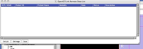
To list the images available in the ImageMetaServer, open the remote data list window from the pull-down menu in the Data I/O Configurations frame in the OpenIGTLinkIF module. The pull-down menu appears when you right-click on the connector node (vtkMRMLIGTLConnectorNode1 in default) in the tree interface as shown in the images bellow.
Click Get List button on the remote data list window. A list of images show up on the window.
