OpenIGTLink/Slicer
Contents
Overview
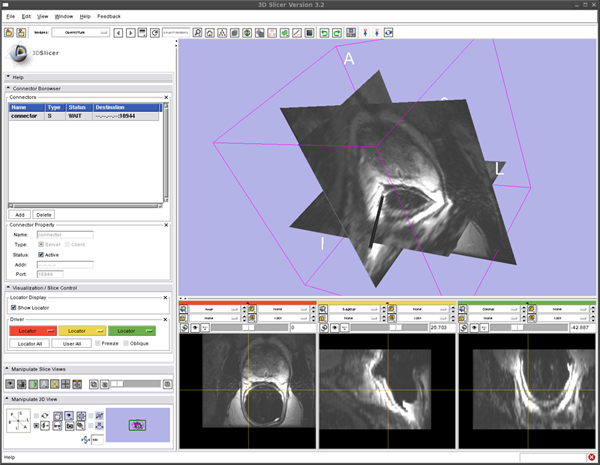
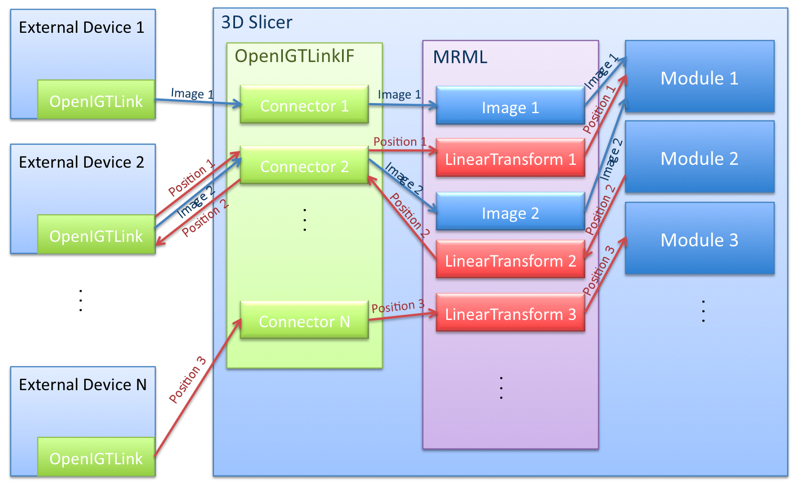
The 3D Slicer OpenIGTLink Interface Module is a program module for that can handle network communications between 3D Slicer and external software / hardware using OpenIGTLink protocol. The module provides following functions:
- Data import: The module can import position, linear transform and image data from OpenIGTLink-compliant software / hardware to the MRML scene.
- Data export: The module can export linear transform and image data from the MRML scene.
- Multi-connection: The module can manage multiple OpenIGTLink connections at the same time.
- Locator visualization: The user can choose one of linear transforms in the MRML scene to visualize its position and orientation in the 3D space.
- Slice driving: The module can control volume re-slicing plane based on linear transform in the MRML scene.
Architecture
Install the Software
From binaries
The module is available only in Slicer 3.3 source distribution. For Slicer 3.2, please see old page.
Build from the source
Building instruction can be found in OpenIGTLink/Slicer/Build.
Install Tracker Simulator to Testing the OpenIGTlink interface module
To test the OpenIGTLink interface module (or other OpenIGTLinkcomplaint devices and software), tracking simulator software is provided as an example program of the OpenIGTLink library (note that the OpenIGTLink library is different from the OpenIGTLink interface module in 3D Slicer).
From binaries
Obtain a binary file for your environment.
- For Linux (x86, 32-bit).
- For Linux (x86, 64-bit).
- For Windows (32-bit).
- For Mac OS X (x86).
- For Mac OS X (PPC).
From Source
The instruction can be found in OpenIGTLink/Library/build. Please make sure that you enable "build examples" option.
Testing Open IGT Link Module -- Show Tracking Device in the 3D Space
Set up Open IGT Link Module
- Select "OpenIGTLink" from "Modules:" menu
- Open "Connector Browser" frame, and press "Add" button below the "Connectors" list to add a new connector
- Configure and start the connector. Choose "Server" check box in the "Type" option, then clinck "Active" check box. Now the Slicer is ready to accept connections through Open IGT Link.
Run Tracker Simulator
To send dummy coordinate data to the Slicer running on localhost with frame rate of 10 fps, run:
$ ./TrackerSim 10 c localhost 18944
Visualize Tracker Position
To see the coordinate from the Tracker Simulator,
- Open "Visualization / Slice Control" frame in the OpenIGTLink module interface.
- Click the "Show Locator" check button. A locator model shows up on the 3D viewer.
- Open "Data" module. Choose "Data" from "Modules:" menu.
- Edit MRML tree. Put "IGTLocator" under the "Tracker" by dragging "IGTLocator" node.
- You should see the locator model moves in the 3D viewer.
Testing Open IGT Link Module -- Reslice 3D image
We can reslice 3D image according to the locator position with following steps:
- Load 3D volume from the "Volumes" module.
- Start Tracking as we did in the previous section.
- In the "Visualization / Slice Control" frame in the OpenIGTLink module interface, click Red menu and choose "Locator".
- The image in the left 2D slice viewer (Red) should start to move. You can change the orientation by changing slice orientation menu in the 2D slice viewer.
- If you click the "Oblique" check button in the "Visualization / Slicer Control" frame, the slice orientation is set according to the locator orientation.
- You can use other 2D viewers (Yellow and Green) by choosing "Locator" from the Yellow and Green menu in the "Visualization / Slice Control" frame.
Loadmap

