2009 Summer Project Week Transrectal Prostate biopsy
From NAMIC Wiki
Home < 2009 Summer Project Week Transrectal Prostate biopsy
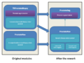
Overview of the ProstateNav / TRProstateBiopsy module rework.
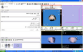
ProstateSeg module: seeds.
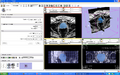
ProstateSeg module: segmentation result.
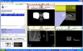
Result of a needle insertion experiment on a phantom, using Slicer with a transrectal prostate biopsy robot.


Key Investigators
- Gabor Fichtinger, Andras Lasso (lasso@cs.queensu.ca), Siddharth Vikal; Queen’s University
- Allen Tannenbaum, Yi Gao; Georgia Tech
- Nobuhiko Hata, Junichi Tokuda; BWH
Objective
- Rework current prostate biopsy modules (TRProstateBiopsy and ProstateNav)
- Create a new standalone module (ProstateSeg) for prostate segmentation, with the latest version of the algorithms, that can be used from the robot modules or in itself.
- Merge the two prostate robot modules: This will reduce the total amount of code, make it easier to reuse features developed by different teams for different robots, make the testing and bugfixing more efficient, makes possible to support new robots, scanners, and procedures in the future.
Approach, Plan
- Prostate segmentation: There are two algorithms (Algorithm 1: Shape based segmentation. The shape of prostates are learned and then the new image is segmented using the shapes learned. Algorithm 2: It is based on the Random Walks segmentation algorithm. It need more human input but the result could be interactively improved arbitrarily close to user's expectation.), integrate them into a standalone module.
- Prostate robotics: Merge the existing modules (select one prostate robotics module as a base, clean it up, design generic robot and scanner interfaces, and integrate functions and specific robot/scanner support parts from the other module), so that all the functionalities will be available for all robots.
Progress
- Created ProstateSeg module (available in NAMIC SandBox; command line module, can be used without ProstateNav).
- Tested on clinical images. Typical computation time is about 10 seconds (requires manually defined seed and background area).
- Identified potential solutions for automatic seed and background area definition.
- Tested the Slicer module in a phantom experiment at B&W. Needle placement error was 1.7mm (needle trajectory distance from target).
- Agreed in high level design for transrectal and transperineal ProstateNav module merge.
- Prepared the ProstateNav module for the merge (cleaned up the module to contain only device indpendent parts).
Future steps
- ProstateSeg module
- Explore shape based method with new dataset (-July 19)
- Update the tutorial
- Determine seed points and background points automatically (e.g., image center is in prostate, determine approximate bounding sphere for prostate, use shrinked sphere as seed, expanded sphere for background)
- Improve segmentation accuracy (prevent leaking)
- Performance improvement
- Reuse current result volume as an initial value for the solution to speed up computations after some changes (adding more seed points or background points)
- Use multiresolution technique to get a quick approximate result (then use that result as initial value for the full-resolution computation)
- Make use of segmentation on pre-operative images
- ProstateNav module
- Merge TRProstateBiopsy features into ProstateNav
- Configuration: configure the module (mostly wizard steps) to use the module for different procedures/devices
- Wizard steps:
- Start up: select a configuration XML file and check devices, connections. The XML file contains:
- Robot model
- OpenIGTLink address, DICOM directory/server
- Needles
- Screen configuration
- Calibration
- Targeting: driving needle to reach targets
- Manual: manual robot/scanner control
- Verification
- Start up: select a configuration XML file and check devices, connections. The XML file contains:
- Classes
- ProstateBiopsyRobotNode (MRMLNode): holds all robot data (current position, current needle, available needles, status, visualization options?, calibration data), sending command to robot
- RobotDisplayWidget: observes ProstateBiopsyRobotNode and displays the robot in the viewer; specific for each robot, show/hide arm, needle, coverage, calibration object
- ProstateBiopsyNode (MRMLNode): contain all configuration data, OpenIGTLink, DICOM links, screen config, link to the target list (fiducial list), additional properties for each target (which needle, already completed, etc. – one common superclass to hold data for one target)
- SetupStep
- CalibrationStep: robot specific, there should be a common superclass
- TargetingStep
- VerificationStep
- ManualStep: robot specific
- User interface
- Secondary monitor support
- Communication
- OpenIGTLink for direct scanner connection
- OpenIGTLink for DICOM communication with the Scanner
References
- Grady, Leo “Random walks for Image Segmentation” IEEE-PAMI 2006
- S Vikal, Steven Haker, Clare Tempany, Gabor Fichtinger, Prostate contouring in MRI guided biopsy, SPIE Medical Imaging 2009: Image Processing, Proc. SPIE, Vol. 7259, 72594A, 2009
- S. Vikal, S. Haker, C. Tempany, G Fichtinger, Prostate contouring in MRI guided biopsy, Workshop on Prostate image analysis and computer-assisted intervention, held in conjunction with the 11th International Conference on Medical Image Computing and Computer Assisted Intervention – MICCAI, September 2008.
- Singh AK, Guion P, Sears Crouse N, Ullman K, Smith S, Albert PS, Fichtinger G, Choyke PL, Xu S, Kruecker J, Wood BJ, Krieger A, Ning H, “Simultaneous Integrated Boost of Biopsy Proven, MRI Defined Dominant Intra-prostatic Lesions to 95 Gray with IMRT: Early Results of a Phase I NCI Study”, Radiat Oncol. 2007 Sep 18;2(1)
- Singh AK, Krieger A, Lattouf JB, Guion P, Grubb III RL, Albert PS, Metzger G, Ullman K, Fichtinger G, Ocak I, Choyke PL, Ménard C, Coleman J, “Patient Selection Appears To Determine Prostate Cancer Yield Of Dynamic Contrast Enhanced MRI Guided Transrectal Biopsies In A Closed 3 Tesla Scanner”, British Journal of Urology, 2007 Oct 8;