Difference between revisions of "Projects:RegistrationLibrary:RegLib A01"
From NAMIC Wiki
(Created page with '= Registration Library : Using Grid Images = #Match physical dimensions & position ##Load grid image with the desired number of grid points (e.g. ~50% higher than the DOF of the …') |
m (Text replacement - "http://www.slicer.org/slicerWiki/index.php/" to "https://www.slicer.org/wiki/") |
||
| (9 intermediate revisions by one other user not shown) | |||
| Line 1: | Line 1: | ||
| + | [[Projects:RegistrationDocumentation|Back to Registration main page]] | ||
| + | [[Projects:RegistrationDocumentation:UseCaseInventory|Back to Registration Use-case Inventory]] | ||
| + | [[Projects:RegistrationDocumentation:UseCaseInventory:Auxiliary|Back to Auxiliary Data collection]] | ||
= Registration Library : Using Grid Images = | = Registration Library : Using Grid Images = | ||
| − | + | 1.Match physical dimensions & position | |
##Load grid image with the desired number of grid points (e.g. ~50% higher than the DOF of the BSpline applied) | ##Load grid image with the desired number of grid points (e.g. ~50% higher than the DOF of the BSpline applied) | ||
##Place your target image in background and grid image in foreground | ##Place your target image in background and grid image in foreground | ||
| − | ##Go to ''Volumes'' module / Info tab | + | ##Go to ''Volumes'' module / ''Info'' tab |
##select first target and then grid image from ''Active Volume'' menu; for both click on ''Center Volume'' button to match image centers | ##select first target and then grid image from ''Active Volume'' menu; for both click on ''Center Volume'' button to match image centers | ||
##set fading slider to halfway, so you can see both target and grid image | ##set fading slider to halfway, so you can see both target and grid image | ||
##select grid image from ''Active Volume'' menu | ##select grid image from ''Active Volume'' menu | ||
| − | ##change ''Image Spacing'' parameters (voxel size) to something close to those of your target image. You will see the grid change shape as you adjust. Make numbers smaller or larger to change the box sizes. | + | ##change ''Image Spacing'' parameters (voxel size) to something close to those of your target image. You will see the grid change shape as you adjust. Make numbers smaller or larger to change the box sizes. Click the ''Center Volume'' button after each size adjustment. Continue until grid largely covers area of interest |
| − | + | [[Image:ImageSpacing.png|300px|center]] | |
| − | ##go to [ | + | [[Image:ColorGrid_overlay.png|500px|center]] |
| + | |||
| + | ---- | ||
| + | |||
| + | 2.Deform | ||
| + | ##go to [https://www.slicer.org/wiki/Modules:ResampleScalarVectorDWIVolume-Documentation-3.6 ''ResampleScalarVectorDWIVolume''] module (Filtering menu) | ||
##select grid image as input, your target as reference | ##select grid image as input, your target as reference | ||
##select "create new volume" from output volume and rename to "grid_deformed" or similar | ##select "create new volume" from output volume and rename to "grid_deformed" or similar | ||
##under ''Transform Node'' select the nonrigid (BSpline) transformation | ##under ''Transform Node'' select the nonrigid (BSpline) transformation | ||
| + | ##as interpolation method, select "nearest neighbor". If continuity of the deformed grid lines is important, select "linear" | ||
##leave rest at defaults; click ''Apply''. | ##leave rest at defaults; click ''Apply''. | ||
| + | [[Image:BWGrid_overlay_deformed.png|200px|center]] | ||
| + | [[Image:ColorGrid_overlay_deformed.png|500px|center]] | ||
| + | ---- | ||
| + | |||
| + | 3.Evaluate | ||
| + | *the grid images have different values for the axial, sagittal and coronal planes to help you distinguish. An orthogonal plane being bent down into an adjacent slice shows up as rings or blobs. You can adjust the window & level values to match the particular plane and thus fade out the distracting other ones. Or you can threshold the grid image to generate labelmaps that contain only 1 set of planes for easier viewing. | ||
| + | *the alternative 4D grid image contain each plane as a separate channel and are loaded as vector images that will show up in color (see figure above) that help distinguish the different directions. | ||
| + | |||
| + | = Registration Library : Using Deformation Field Images = | ||
| + | '''1.Build/convert''' | ||
| + | *There is commandline functionality in Slicer to convert a BSpline ITK transform file (.tfm) into a deformation field volume. To execute, type (exchange ''/Applications/Slicer3.6.3'' with the path of your Slicer installation): | ||
| + | /Applications/Slicer3.6.3/Slicer3 --launch /Applications/Slicer3.6.3/lib/Slicer3/Plugins/BSplineToDeformationField --tfm InputBSpline.tfm | ||
| + | --refImage ReferenceImage.nrrd --defImage Output_DeformationField.nrrd | ||
| + | *for more details try: | ||
| + | /Applications/Slicer3.6.3/Slicer3 --launch /Applications/Slicer3.6.3/lib/Slicer3/Plugins/BSplineToDeformationField --help | ||
| + | *this creates a 4-dimensional (4D) image that contains the displacements of each image point in the x-, y- and z-direction as 3 separate volumes. You can load this image into Slicer and visualize the distribution and values of the deformation field. If loaded as a NRRD "list" image (as of v.3.6.3 there was a problem with loading 4D "vector" NRRD images, so if you have trouble loading, try changing the following line in the NRRD header, e.g. with a text editor: | ||
| + | sizes: 3 256 256 124 | ||
| + | space directions: none (0.9375,0,0) (0,0,-0.9375) (0,-1.5,0) | ||
| + | kinds: vector domain domain domain | ||
| + | change the word "vector" to the word "list" and then save and retry loading: | ||
| + | kinds: list domain domain domain | ||
| + | |||
| + | ---- | ||
| + | <br> | ||
| + | |||
| + | '''2. Visualize''' | ||
| + | [[Image: RegLib_DefFieldColor.png|200px|Example of 4D displacement field rendered in Slicer. displacements in the x-, y- and z-direction in red, green and blue color, respectively.]] | ||
| + | *if loaded properly, the 4D volume is rendered in RGB color, with displacements in the x-, y- and z-direction in red, green and blue color, respectively. RGB mixtures of yellow, cyan and magenta then indicate displacements of similar magnitude in both xy, yz and xz directions, respectively etc. | ||
| + | *Note that negative displacements (as of v.3.6) are clipped and will all show as black. | ||
Latest revision as of 18:07, 10 July 2017
Home < Projects:RegistrationLibrary:RegLib A01Back to Registration main page Back to Registration Use-case Inventory Back to Auxiliary Data collection
Registration Library : Using Grid Images
1.Match physical dimensions & position
- Load grid image with the desired number of grid points (e.g. ~50% higher than the DOF of the BSpline applied)
- Place your target image in background and grid image in foreground
- Go to Volumes module / Info tab
- select first target and then grid image from Active Volume menu; for both click on Center Volume button to match image centers
- set fading slider to halfway, so you can see both target and grid image
- select grid image from Active Volume menu
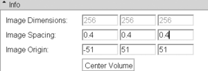
- change Image Spacing parameters (voxel size) to something close to those of your target image. You will see the grid change shape as you adjust. Make numbers smaller or larger to change the box sizes. Click the Center Volume button after each size adjustment. Continue until grid largely covers area of interest
2.Deform
- go to ResampleScalarVectorDWIVolume module (Filtering menu)
- select grid image as input, your target as reference
- select "create new volume" from output volume and rename to "grid_deformed" or similar
- under Transform Node select the nonrigid (BSpline) transformation
- as interpolation method, select "nearest neighbor". If continuity of the deformed grid lines is important, select "linear"
- leave rest at defaults; click Apply.
3.Evaluate
- the grid images have different values for the axial, sagittal and coronal planes to help you distinguish. An orthogonal plane being bent down into an adjacent slice shows up as rings or blobs. You can adjust the window & level values to match the particular plane and thus fade out the distracting other ones. Or you can threshold the grid image to generate labelmaps that contain only 1 set of planes for easier viewing.
- the alternative 4D grid image contain each plane as a separate channel and are loaded as vector images that will show up in color (see figure above) that help distinguish the different directions.
Registration Library : Using Deformation Field Images
1.Build/convert
- There is commandline functionality in Slicer to convert a BSpline ITK transform file (.tfm) into a deformation field volume. To execute, type (exchange /Applications/Slicer3.6.3 with the path of your Slicer installation):
 /Applications/Slicer3.6.3/Slicer3 --launch /Applications/Slicer3.6.3/lib/Slicer3/Plugins/BSplineToDeformationField --tfm InputBSpline.tfm
  --refImage ReferenceImage.nrrd   --defImage Output_DeformationField.nrrd
- for more details try:
/Applications/Slicer3.6.3/Slicer3 --launch /Applications/Slicer3.6.3/lib/Slicer3/Plugins/BSplineToDeformationField --help
- this creates a 4-dimensional (4D) image that contains the displacements of each image point in the x-, y- and z-direction as 3 separate volumes. You can load this image into Slicer and visualize the distribution and values of the deformation field. If loaded as a NRRD "list" image (as of v.3.6.3 there was a problem with loading 4D "vector" NRRD images, so if you have trouble loading, try changing the following line in the NRRD header, e.g. with a text editor:
 sizes: 3 256 256 124
 space directions: none (0.9375,0,0) (0,0,-0.9375) (0,-1.5,0)
 kinds: vector domain domain domain
change the word "vector" to the word "list" and then save and retry loading:
kinds: list domain domain domain
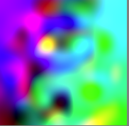
- if loaded properly, the 4D volume is rendered in RGB color, with displacements in the x-, y- and z-direction in red, green and blue color, respectively. RGB mixtures of yellow, cyan and magenta then indicate displacements of similar magnitude in both xy, yz and xz directions, respectively etc.
- Note that negative displacements (as of v.3.6) are clipped and will all show as black.


