Difference between revisions of "Projects:RegistrationLibrary:RegLib C29"
From NAMIC Wiki
| Line 118: | Line 118: | ||
*TUTORIALS: | *TUTORIALS: | ||
**[[Media:RegLib_C29_Screencast.mov| Screencast movie (Quicktime, 73 MB)]] | **[[Media:RegLib_C29_Screencast.mov| Screencast movie (Quicktime, 73 MB)]] | ||
| − | **[[Media: | + | **[[Media:RegLib_C29_DTI.ppt| Powerpoint Tutorial (.ppt PowerPoint file, 1.5 MB)]] |
| − | **[[Media: | + | **[[Media:RegLib_C29_DTI.pdf| Powerpoint Tutorial as PDF (PDF file 2.1 MB)]] |
Revision as of 21:14, 7 September 2010
Home < Projects:RegistrationLibrary:RegLib C29Back to ARRA main page
Back to Registration main page
Back to Registration Use-case Inventory
Contents
v3.6.1  Slicer Registration Library Case #29: Intra-subject Brain DTI
Input
|
|
|
|
|
|
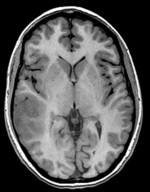
| fixed image/target T1 SPGR |
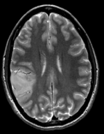
moving image 1 T2 |
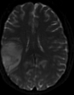
moving image 2a DTI baseline |
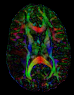
moving image 2b DTI tensor |
Modules
- Slicer 3.6.1 recommended modules: BrainsFit
Objective / Background
This is a classic case of a multi-sequence MRI exam we wish to spatially align to the anatomical reference scan (T1-SPGR). The scan of interest is the DTI image to be aligned for surgical planning/reference.
Keywords
MRI, brain, head, intra-subject, DTI, T1, T2, non-rigid, tumor, surgical planning
Input Data
- reference/fixed : T1 SPGR , 0.5x0.5x1 mm voxel size, 512 x 512 x 176
- moving 1: T2 0.5x0.5x1.5 mm voxel size, 512 x 512 x 92
- moving 2a: DTI baseline: 1 x 1 x 3 mm, 256 x 256 x 41
- moving 2b: 1 x 1 x 3 mm, 256 x 256 x 41 x 9 (tensor), original: DWI 256 x 256 x 41 x 32 directions
Registration Challenges
- The DTI sequence (EPI) contains string distortions we seek to correct via non-rigid alignment
- the DTI baseline is similar in contrast to a T2, albeit at much lower resolution
- we have different amounts of voxel-anisotropy
- a direct registration of the DTI_baseline to the SPGR will fail, hence a 2-step approach is required
Key Strategies
- Slicer 3.6.1 recommended modules: BrainsFit
- we use an 2-step approach: 1) we first co-register the T2 with the SPGR T1. 2) we register the DTI baseline to the T2 (the T1 provides insufficient similarity), 3) combine this with the Affine1 transform obtained from registering the T2 to the T1. affine transform with 12 DOF (rather than a rigid one) to address distortion differences between the two protocols; 4) resample the DTI volume with the new transform
Procedures
- Phase I: LOAD DATA
- download example dataset
- load into 3DSlicer 3.6.1 (Load Scene)
- To convert the DWI into a DTI: use the Converters / DICOM to NRRD Converter module
- Phase II:REGISTER DTI TO T2
- open Registration : BrainsFit module
- Registration Phases:
- set T2 as fixed and DTI_baseline as moving image
- select/check Include Rigid registration phase
- select/check Include Affine registration phase
- select/check Include BSpline registration phase
- select Initialize with CenterofHeadAlign
- select Include Rigid registration phase
- select "Include Affine registration phase"
- Output Settings:
- select a new transform "Slicer BSpline Transform"
- select a new volume "Output Image Volume
- Registration Parameters: increase Number Of Samples to 200,000
- Leave all other settings at default
- click apply; runtime ca. 3 min.
- Phase III: Register T2 to SPGR
- open Registration : BrainsFit module
- Registration Phases:
- select/check Include Rigid registration phase
- select/check Include Affine registration phase
- select a new transform Output Transform
- Registration Parameters: increase Number Of Samples to 200,000
- Leave all other settings at default
- click apply; runtime ca. 1-2 min.
- Phase IV: Merge transforms
- We now have an affine transform to align the T2 with the SPGR and an BSpline+Affine to align the DTIBaseline with the T2
- there are 2 alternatives:
- Resample the DTI twice consecutively with each transform
- Combine the transforms and resample only once. This is the preferred approach since it reduces interpolation blurring. However this requires editing the transform file. The affine portion of the BSpline transform needs to be extracted, combined with the T2-SPGR affine and then reinserted; as described below:
- Select Save, select the BSpline and the Affine transforms to be saved
- in a Text Editor of your choice (outside Slicer), open the BSpline transform file and delete the BSpline portion Transform 0. Then Save As.. 'under a new name.
- Reload the newly edited transform into slicer, named e.g. as DTIBaseline_Affine0 (via Add Data)
- Move it inside the other affine transform that aligns the T2 to the SPGR.
- Select Harden Transforms'
- Save the newly "hardened/combined" transform to a file, e.g. named DTI2T1_AffineOnly.tfm
- in a Text Editor of your choice (outside Slicer), open again the BSpline transform file and also the above DTI2T1_AffineOnly.tfm
- replace the affine portion in the BSpline file with the affine portion of DTI2T1_AffineOnly.tfm and save under a new name,e.g. DTI2T1_combined.tfm
- This is now the new transform that will resample the DTI directly to the SPGR (see phase V below)
- Phase V: Resample DTI
- Load the combined transform (Add Data)
- Open the Resample DTI Volume module (found under: All Modules)
- Input Volume: select DTI
- Output Volume: select New DTI Volume, rename to DTI_reg2T1
- Reference Volume: select SPGR
- Transform Parameters: select merged transform DTI2T1_combined.tfm
- check box: output-to-input
- Leave all other settings at defaults
- Click Apply; runtime ca. 3-4 min.
- Go to the Volumes module, select the newly produced DTI_reg2T1 volume
- under the Display tab, select Color Orientation from the Scalar Mode menu
- set SPGR as background and new DTI_reg2T1 volume as foreground
- Set fade slider to see DTI overlay onto the SPGR image
for more details see the tutorial(s) under Downloads
Registration Results
Registered DTI superimposed on SPGR and T2 registered (cycles show T1 and T2 and color DTI overlay)
Download
- DATA
- PRESETS:
- TUTORIALS: