Difference between revisions of "Projects:RegistrationLibrary:RegLib C03"
From NAMIC Wiki
| Line 45: | Line 45: | ||
#download example dataset | #download example dataset | ||
#load into 3DSlicer 3.6.1 (Load Scene) | #load into 3DSlicer 3.6.1 (Load Scene) | ||
| − | #To convert | + | #To convert a DWI into a DTI: use the ''Converters / DICOM to NRRD Converter'' module |
| − | *'''Phase | + | *'''Phase I:REGISTER DTI_base TO T2''' |
#open Registration : ''BrainsFit'' module | #open Registration : ''BrainsFit'' module | ||
##Registration Phases: | ##Registration Phases: | ||
| − | ## | + | ##set T2 as fixed and DTI_base as moving image |
| − | + | ###select/check ''Initialize Center of Head Align'' | |
| − | |||
| − | |||
| − | |||
| − | |||
| − | |||
| − | |||
| − | |||
| − | |||
| − | |||
| − | ## | ||
| − | # | ||
| − | |||
| − | |||
| − | |||
| − | |||
| − | |||
| − | |||
###select/check ''Include Rigid registration phase'' | ###select/check ''Include Rigid registration phase'' | ||
###select/check ''Include Affine registration phase'' | ###select/check ''Include Affine registration phase'' | ||
###select/check ''Include BSpline registration phase'' | ###select/check ''Include BSpline registration phase'' | ||
| − | |||
| − | |||
| − | |||
##Output Settings: | ##Output Settings: | ||
| − | ###select a new transform "Slicer BSpline Transform", rename to " | + | ###select a new transform "Slicer BSpline Transform", rename to "Xf1_DTI-T2_unmasked" |
| − | ###select a new volume "Output Image Volume'', rename to " | + | ###select a new volume "Output Image Volume'', rename to "DT_base_Xf1" |
##Registration Parameters: increase ''Number Of Samples'' to 200,000 | ##Registration Parameters: increase ''Number Of Samples'' to 200,000 | ||
##Registration Parameters: set ''Number Of Grid Subdivisions'' to 5,5,3 | ##Registration Parameters: set ''Number Of Grid Subdivisions'' to 5,5,3 | ||
##Leave all other settings at default | ##Leave all other settings at default | ||
##click: Apply; runtime < 1 min. | ##click: Apply; runtime < 1 min. | ||
| − | *'''Phase | + | *'''Phase II: Resample DTI_mask''' |
| − | **we use the above Xform to produce a mask for the | + | **we use the above Xform to produce a mask for the T2. |
#Open ''Resample Scalar/Vector/DWI Volume'' module | #Open ''Resample Scalar/Vector/DWI Volume'' module | ||
| − | ##Input Volume: DTI_mask; Output volume: create new volume, rename to " | + | ##Input Volume: DTI_mask; Output volume: create new volume, rename to "DTI_mask_Xf1" |
| − | ##Transform Node: " | + | ##Transform Node: "Xf1_DTI-T1_unmasked" |
##select/check: ''output-to-input'' | ##select/check: ''output-to-input'' | ||
##Interpolation Type: select: '''nn''' | ##Interpolation Type: select: '''nn''' | ||
##click: Apply | ##click: Apply | ||
| − | *'''Phase | + | ##Go to ''Volumes'' module, select the new "DTI_mask_Xf1", in the ''Info'' tab, check the ''Labelmap'' box |
| + | *'''Phase III:REGISTER DTI TO T2 with masking''' | ||
#open Registration : ''BrainsFit'' module | #open Registration : ''BrainsFit'' module | ||
| − | |||
##set T2_Xf1 as fixed and DTI_baseline as moving image | ##set T2_Xf1 as fixed and DTI_baseline as moving image | ||
| − | ## | + | ###Initialize with transform: select "Xf1_DTI-T2_unmasked" |
| − | ##Output BSpline Transform: create new , rename to " | + | ###select/check ''Include Affine registration phase'' |
| − | ##Output Volume: create new, rename to " | + | ###select/check ''Include BSpline registration phase'' |
| + | ##Output BSpline Transform: create new , rename to "Xf2_DTI-T1_masked" | ||
| + | ##Output Volume: create new, rename to "DTI_base_Xf2" | ||
| + | ##Registration Parameters: increase ''Number Of Samples'' to 200,000 | ||
| + | ##Registration Parameters: set ''Number Of Grid Subdivisions'' to 7,7,5 | ||
##Control of Mask Processing | ##Control of Mask Processing | ||
###select/check: ''ROI'' (rightmost box) | ###select/check: ''ROI'' (rightmost box) | ||
| − | ###Input Fixed Mask: select " | + | ###Input Fixed Mask: select "DTI_mask_Xf1" |
###Input Moving Mask: select "DTI_mask" | ###Input Moving Mask: select "DTI_mask" | ||
| + | ##Leave all other settings at default | ||
##click: Apply; runtime < 1 min. | ##click: Apply; runtime < 1 min. | ||
*'''Phase VI: Resample DTI''' | *'''Phase VI: Resample DTI''' | ||
| Line 106: | Line 91: | ||
##Input Volume: select DTI | ##Input Volume: select DTI | ||
##Output Volume: select ''New DTI Volume'', rename to ''DTI_Xf2'' | ##Output Volume: select ''New DTI Volume'', rename to ''DTI_Xf2'' | ||
| − | ##Reference Volume: select '' | + | ##Reference Volume: select ''T2'' |
| − | ##Transform Parameters: select transform "Xf2_DTI- | + | ##Transform Parameters: select transform "Xf2_DTI-T2_masked'' |
##check box: ''output-to-input'' | ##check box: ''output-to-input'' | ||
##Leave all other settings at defaults | ##Leave all other settings at defaults | ||
| Line 114: | Line 99: | ||
#under the ''Display'' tab, select ''Color Orientation'' from the ''Scalar Mode'' menu | #under the ''Display'' tab, select ''Color Orientation'' from the ''Scalar Mode'' menu | ||
#set ''T1'' as background and new ''DTI_Xf2'' volume as foreground | #set ''T1'' as background and new ''DTI_Xf2'' volume as foreground | ||
| − | #Set fade slider to see DTI overlay onto the | + | #Set fade slider to see DTI overlay onto the T2 image |
for more details see the tutorial(s) under Downloads | for more details see the tutorial(s) under Downloads | ||
Revision as of 21:55, 16 September 2010
Home < Projects:RegistrationLibrary:RegLib C03Back to ARRA main page
Back to Registration main page
Back to Registration Use-case Inventory
Slicer Registration Library Exampe #3: Diffusion Weighted Image Volume: align with structural reference MRI
Input
|
|
|
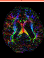
|
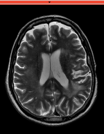
| fixed image/target T2 |
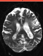
moving image 2a DTI baseline |
moving image 2b DTI tensor |
Modules
- Slicer 3.6.1 recommended modules: BrainsFit
Objective / Background
This is a typical example of DTI processing. Goal is to align the DTI image with a structural scan that provides accuracte anatomical reference. The DTI contains acquisition-related distortion and insufficient contrast to discern anatomical detail.
Keywords
MRI, brain, head, intra-subject, DTI, DWI
Download
- download entire package (Data,Presets, Solution, zip file 24 MB)
- Presets
- Tutorial only
- Image Data only
Link to User Guide: How to Load/Save Registration Parameter Presets
Input Data
 reference/fixed : T2w axial, 0.4mm resolution in plane, 3mm slices
 moving: Baseline image of acquired DTI volume, corresponds to T2w MRI , 0.9375 x 0.9375 x 1.4 mm voxel size, oblique
 tag: Tensor data of DTI volume, oblique, same orientation as Baseline image. The result Xform will be applied to this volume. The original DWI has 26 directions, the extracted DTI volume has 9 scalars, i.e. 256 x 256 x 36 x 9
Procedures
- Phase I: LOAD DATA
- download example dataset
- load into 3DSlicer 3.6.1 (Load Scene)
- To convert a DWI into a DTI: use the Converters / DICOM to NRRD Converter module
- Phase I:REGISTER DTI_base TO T2
- open Registration : BrainsFit module
- Registration Phases:
- set T2 as fixed and DTI_base as moving image
- select/check Initialize Center of Head Align
- select/check Include Rigid registration phase
- select/check Include Affine registration phase
- select/check Include BSpline registration phase
- Output Settings:
- select a new transform "Slicer BSpline Transform", rename to "Xf1_DTI-T2_unmasked"
- select a new volume "Output Image Volume, rename to "DT_base_Xf1"
- Registration Parameters: increase Number Of Samples to 200,000
- Registration Parameters: set Number Of Grid Subdivisions to 5,5,3
- Leave all other settings at default
- click: Apply; runtime < 1 min.
- Phase II: Resample DTI_mask
- we use the above Xform to produce a mask for the T2.
- Open Resample Scalar/Vector/DWI Volume module
- Input Volume: DTI_mask; Output volume: create new volume, rename to "DTI_mask_Xf1"
- Transform Node: "Xf1_DTI-T1_unmasked"
- select/check: output-to-input
- Interpolation Type: select: nn
- click: Apply
- Go to Volumes module, select the new "DTI_mask_Xf1", in the Info tab, check the Labelmap box
- Phase III:REGISTER DTI TO T2 with masking
- open Registration : BrainsFit module
- set T2_Xf1 as fixed and DTI_baseline as moving image
- Initialize with transform: select "Xf1_DTI-T2_unmasked"
- select/check Include Affine registration phase
- select/check Include BSpline registration phase
- Output BSpline Transform: create new , rename to "Xf2_DTI-T1_masked"
- Output Volume: create new, rename to "DTI_base_Xf2"
- Registration Parameters: increase Number Of Samples to 200,000
- Registration Parameters: set Number Of Grid Subdivisions to 7,7,5
- Control of Mask Processing
- select/check: ROI (rightmost box)
- Input Fixed Mask: select "DTI_mask_Xf1"
- Input Moving Mask: select "DTI_mask"
- Leave all other settings at default
- click: Apply; runtime < 1 min.
- set T2_Xf1 as fixed and DTI_baseline as moving image
- Phase VI: Resample DTI
- Load the combined transform (Add Data)
- Open the Resample DTI Volume module (found under: All Modules)
- Input Volume: select DTI
- Output Volume: select New DTI Volume, rename to DTI_Xf2
- Reference Volume: select T2
- Transform Parameters: select transform "Xf2_DTI-T2_masked
- check box: output-to-input
- Leave all other settings at defaults
- Click Apply; runtime < 1 min.
- Go to the Volumes module, select the newly produced DTI_Xf2 volume
- under the Display tab, select Color Orientation from the Scalar Mode menu
- set T1 as background and new DTI_Xf2 volume as foreground
- Set fade slider to see DTI overlay onto the T2 image
for more details see the tutorial(s) under Downloads
Registration Results
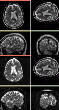
| baseline to T2 after affine alignment |
Discussion: Registration Challenges
- The DTI contains acquisition-related distortions (commonly EPI acquisitions) that can make automated registration difficult.
- the two images often have strong differences in voxel sizes and voxel anisotropy. If the orientation of the highest resolution is not the same in both images, finding a good match can be difficult.
- there may be widespread and extensive pathology (e.g stroke, tumor) that might affect the registration if its contrast is different in the baseline and structural reference scan
Discussion: Key Strategies
- the two images have identical contrast, hence we could consider "sharper" cost functions, such as NormCorr or MeanSqrd. But because of the strong distortions and lower resolution of the moving image, Mutual Information is recommended as the most robust metric.
- often anatomical labels are available from the reference scan. It would be less work to align the anatomical reference with the DTI, since that would circumvent having to resample the complex tensor data into a new orientation. However the strong distortions are better addressed by registering the other direction, i.e. move the DTI into the anatomical reference space.
- because we seek to assess/quantify regional size change, we must use a rigid (6DOF) scheme, i.e. we must exclude scaling.
- masking is likely necessary to obtain good results.
- in this example the initial alignment of the two scans is very poor. The strongly oblique orientation of the DTI makes an initial manual alignment step necessary.
- these two images are not too far apart initially, so we reduce the default of expected translational misalignment
- because speed is not that critical, we increase the sampling rate from the default 2% to 15%.
- we also expect larger differences in scale & distortion than with regular structural scane: so we significantly (2x-3x) increase the expected values for scale and skew from the defaults.
- a good affine alignment is important before proceeding to non-rigid alignment to further correct for distortions.
