Projects:RegistrationLibrary:RegLib C28
From NAMIC Wiki
Revision as of 16:11, 24 March 2011 by Meier (talk | contribs) (Created page with 'Back to ARRA main page <br> Back to Registration main page <br> [[Projects:RegistrationDocumentation:UseCaseInv…')
Home < Projects:RegistrationLibrary:RegLib C28
v3.6.1
Back to ARRA main page
Back to Registration main page
Back to Registration Use-case Inventory
Contents
v3.6.1  Slicer Registration Library Case 28:
In Vitro cerebral body CT (intra subject)
Input

|

|

|
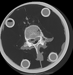
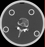
| baseline image | follow-up |
Modules
- Slicer 3.6.1 recommended modules: BRAINSFit
Objective / Background
This dataset contains in vitro CT of two human vertibral body segments (L4) before and after regional damage. Goal is to align the two images to study in detail the local changes that occurred.
Keywords
CT, spine cancer, vertebrae
Issues Challenges
- the baseline container contains the vertebra upside down (as apparent from orientation of the pedicle/roots of the vertibral arches coming out of the body, visible in sagittal or coronal view). Hence this image needs to have its z-axis (IS) reversed before registration
- the containers walls and lid contain dominant image content that would prevent a successful automated registration; cropping is required
- the two vertebrae have strong rotational misalignment; manual initial alignment is recommended
Input Data
- fixed: CT , 0.342 x 0.342 x 0.20 mm voxel size, axial; 512 x 512 x 193 unsigned short image
- moving: CT , 0.342 x 0.342 x 0.20 mm voxel size, axial; 512 x 512 x 250 unsigned short image
Procedure / Pipeline
- Open case scene file or import image data: RegLib_C28_SlicerScene1.mrml
- Place L4_intact and L4_defect in back- and foreground respectively.
- Scroll through sagittal view and note the inverted axis orientation
- Flip axis
- Go to the Data module
- right-click on the Scene node and select "Insert Transform Node" from the menu
- select the newly created transform node, then in the MRML Node Inspector below, rename it to "Xf0_AxialFlip"
- select the "L4_intact" node and drag it inside/on top of the Xf0_AxialFlip" node
- Go to the Transforms module
- Select "Xf0_AxialFlip" from the Transform Node menu
- In the 4x4 matrix displayed, click in the field containing the "1.0000" in row 3 and column 3.
- hit Return key to activate editing
- change the number to -1. Hit Enter.
- you should see the image flip in the sagittal and coronal slice views
- Go to the Data module
- Input Surface: S02_femur
- Target Surface: S01_femur
- Output Transform: create new transform, rename to "Xf1_surf_S2-S1"
- Select/check Mean distance mode: RMS
- Leave defaults: iterations: 50, landmarks: 200
- Select/check Start by matching centroids
- Select/check Check mean distance
- Click: Apply; process duration: ~ seconds
- Go to the Data module
- find the newly created transform node "Xf1_surf_S2-S1" and drag the "S02_femur" model node (and all other S02 entities) inside the transform.
- for the 3D viewer turn on the visibility of the surface models (should be on already)
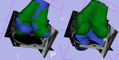
- the surfaces for the two femur models should now align in basic position and orientation
- for additional details see tutorial downloads below
Registration Results
Download
- Data
- Presets
- Link to User Guide: How to Load/Save Registration Parameter Presets
- Documentation
