Projects:RegistrationLibrary:RegLib C32
From NAMIC Wiki
Home < Projects:RegistrationLibrary:RegLib C32
v3.6.1
Back to ARRA main page
Back to Registration main page
Back to Registration Use-case Inventory
Contents
v3.6.1  Slicer Registration Library Case #32: Intra-subject Brain DTI
Input

|

|

|

|
| fixed image 1/target DTI baseline |
fixed image 1/target DTI tensor |
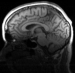
moving image T1 |
Modules
- Slicer 3.6.1 recommended modules: BrainsFit, Skull Stripping Module, N4 MRI Bias Field Correction
Objective / Background
This is a common case of a DTI exam with no T2 available as structural reference and a T1 that has strong field inhomogeneity. In this particular case we seek the inverse alignment of the T1 with the DTI.
Download
- DATA
- PRESETS:
- Documentation:
- See detailed pipeline with parameter settings below
Keywords
MRI, brain, head, intra-subject, DTI, T1, non-rigid,
Input Data
- reference/fixed: DTI baseline: 2.5 x 2.5 x 2.5 mm, 128 x 112 x 44
- reference/fixed: DTI tensor: : 2.5 x 2.5 x 2.5 mm, 128 x 112 x 44 x 9 (tensor), original: DWI 256 x 256 x 41 x 36 directions
- moving : T1 , 1x1x1.1 mm voxel size, 256 x 256 x 193
Registration Challenges
- The DTI sequence (EPI) has a low resolution, a clipped FOV and distortions we seek to correct via non-rigid alignment
- the DTI baseline is similar in contrast to a T2, but we have only a T1 as structural reference
Key Strategies
- Slicer 3.6.1 recommended modules: BrainsFit
- to align the DTI and the T1 we need 2 preprocessing steps: 1. reduce the bias field inhomogeneity in the reference T1 and 2. obtain a skull-stripping / brain mask for the T1
- The DWI is already isotropic and hence no resampling is required before obtaining the DTI
- the T1-DTI registration includes non-rigid deformation to correct for the strong distortions from the EPI acquisition. Because of the nonrigid component a mask of the brain parenchyma helps greatly in obtaining a meaningful transform.
- The DTI estimation provides an automated mask for the DTI_baseline scan, but we have no mask for the T1. We can either obtain one through separate segmentation or by sending the DTI_mask through an additional registration step. We use the former here.
- thus the full pipeline is this:
- Bias Field Correction of T1 -> T1_bc
- Skull Stripping of T1_bc
- DWI -> DTI estimation (incl. DTI_base and DT_mask output)
- Affine registration of T1_bc to DTI_baseline , unmasked
- non-rigid (BSpline) registration of T1_bc to DTI_baseline, masked, using above affine as starting pose
Procedures
- note: for guidance on obtaining the DTI estimate from the DWI see here or the tutorials for Library case #27
- Phase I: LOAD DATA
- download example dataset
- load into 3DSlicer 3.6.1 (Load Scene)
- Note that the main data package does not contain the DWI. Please load separately from the second Data download package.
- Phase II: Bias Correction of T1
- open Filtering : N4ITK MRI Bias Field Correction module
- Input: T1
- Output: create new volume, rename to T1_bc
- Use presets or set parameters: BSpline grid: 2,2,2 ; Shrink Factor: 4
- Click: Apply
- the bias-corrected image will be of type 'float'; to save memory convert to 'uint':
- Open Cast Image module
- Input: T1_bc, Output: T1_bc
- Output Type: unsigned short
- Phase III: Skull Stripping
- Open "Skull Skull Stripper for Structural MR: This is an extension module. If you have never used it before you need to load it first via the extension manager
- Click on the gear wheel icon to the right of the Modules menu. Select the Skull Stripper module and click download and install. Save prelim. work and then restart Slicer to load
- use presets or choose the following settings: Input Volume: T1_bc ; Brain Mask: create new, rename to "T1_mask"; Subdivisions: 20, Dilation Radius: 1
- Phase IVa: Manual Initial Alignment
- the two datasets in this case have very large initial misalignment and also a clipped FOV, which makes it difficult for an automated initializer to find the proper position. This increases the likelihood for the automated registration to go awry. To avoid this we adjust the main (translational) misalignment manually. You may skip this step if your data has closer initial alignment
- Go to the Data module, right-click on the "Scene" node and select "Insert Transform Node"
- select the new transform node and then rename it to "Xf0_ManualInit_T1-DTI", in the MRML Node Inspector" (press return after typing)
- place the DTI_base image in the background and the T1_bc image in the foreground
- move the fade slider halfway to the middle so that you can see both volumes
- go to the Transforms module, move the translation sliders to move the T1 image on top of the DTI, or enter -20 for both LR and IS translation
- in the BRAINSfit module below, select this initialization as starting transform.
- Phase IV: Affine Registration
- you may be able to skip this step and perform affine + nonrigid registration in one step, however the stepwise approach gives you more insight and control
- Go to the BRAINSFit module
- enter the following settings:
- Fixed Image: DTI_base, Moving Image: T1_bc
- Registration phases: from Initialize with previously generated transform', select "Xf0_ManualInit" node created before.
- Registration phases: check boxes for Include Rigid registration phase, Include Scale Versor3D registration phase Include Affine registration phase. To combine with Phase V below also check the Include BSpline phase box.
- Output: Slicer Linear transform: create new, rename to "Xf1_T1-DTI_masked"
- Registration Parameters: increase Number Of Samples to 200,000
- Control Of Mask Processing Tab: check ROI box, Input Fixed Mask : DTI_mask; Input Moving Mask: T1_mask
- Leave all other settings at default
- click apply; runtime ca. 1-2 min.
- go to Data module. You should see the "T1_bc " volume moved inside the "Xf1.." transform node
- select T1_bc as background and DTI_base as foreground and check the alignment via the toggle switch
- Phase V: Nonrigid Registration
- Go to the BRAINSFit module
- enter the following settings:
- Fixed Image: DTI_base, Moving Image: T1_bc
- Registration phases: from Initialize with previously generated transform', select "Xf1_..." node created before.
- Registration phases: check boxes for Include BSpline registration phase
- Output: Slicer BSpline transform: create new, rename to "Xf2_T1-DTI_BSpl"
- Output Image Volume: create new, rename to "T1_bc_Xf2"; Pixel Type: "short"
- Registration Parameters: increase Number Of Samples to 200,000; Number of Grid Subdivisions: 3,3,3
- Control Of Mask Processing Tab: check ROI box, Input Fixed Mask : DTI_mask; Input Moving Mask: T1_mask
- Leave all other settings at default
- click apply; runtime ca. 1-2 min.
- The result volume "T1_bc_Xf2" is the one we want, since the DTI remains stationary, there is no additional resampling required. Note that the final transform "Xf2_T1-DTI_BSpl" contains both the affine and nonrigid BSpline portions.
- To check alignment, go to the Volumes module, select the newly produced DTI volume
- under the Display tab, select Color Orientation from the Scalar Mode menu
- set DTI as background and the new "T1_bc_Xf2" volume as foreground
- Set fade slider to see DTI overlay onto the SPGR image, you should see alignment similar to the result shown below.
